


John Fowler was the father the ploughing engine in the mid 19th century, although one ploughing engine, devised by Peter, Lord Willoughby de Eresby and his bailiff George Gordon Scott and constructed at Swindon Works, was exhibited at the Great Exhibition of 1851 in London, some years before Fowler's system first appeared. Willoughby said that his design could be copied freely, and Fowler visited his estate at Grimsthorpe Castle in Lincolnshire
Fowler’s ploughing engine was a type of traction engine with a large diameter winding drum for wire rope driven by separate gearing from the steam engine. A plough or other implement was hauled across the field by engines at the field edge, minimising the amount of land compacted.
Winding drums were mounted either mounted horizontally (below the boiler), vertically (to one side), or around the boiler. The majority were under-slung requiring a long boiler to allow enough space for the drum to fit between the front and back wheels. They were the largest and longest traction engines to be built.
Generally ploughing engines worked in pairs, one on each side of the field. The two drivers communicated by signals using the engine whistles.
A variety of implements were used with ploughing engines, but the most common were the balance plough and the cultivator. Other implements included the mole drainer, used to create an underground drainage channel or pipe, or a dredger bucket for dredging rivers or moats.
Engines were frequently provided with a 'spud tray' on the front axle, to store the 'spuds' which would be fitted to the wheels when traveling across sticky ground.
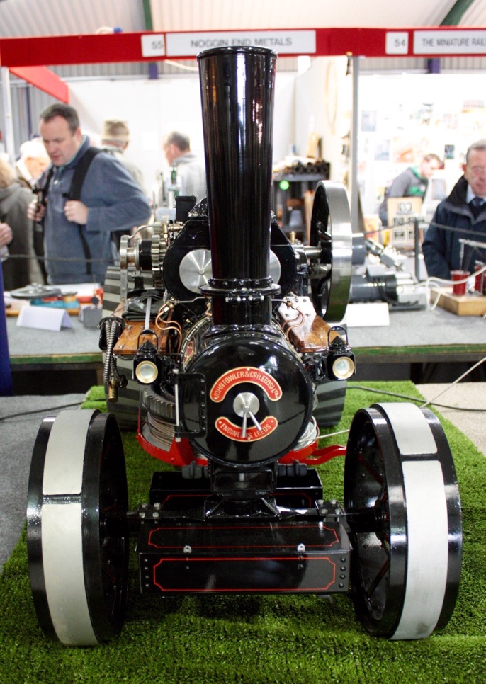
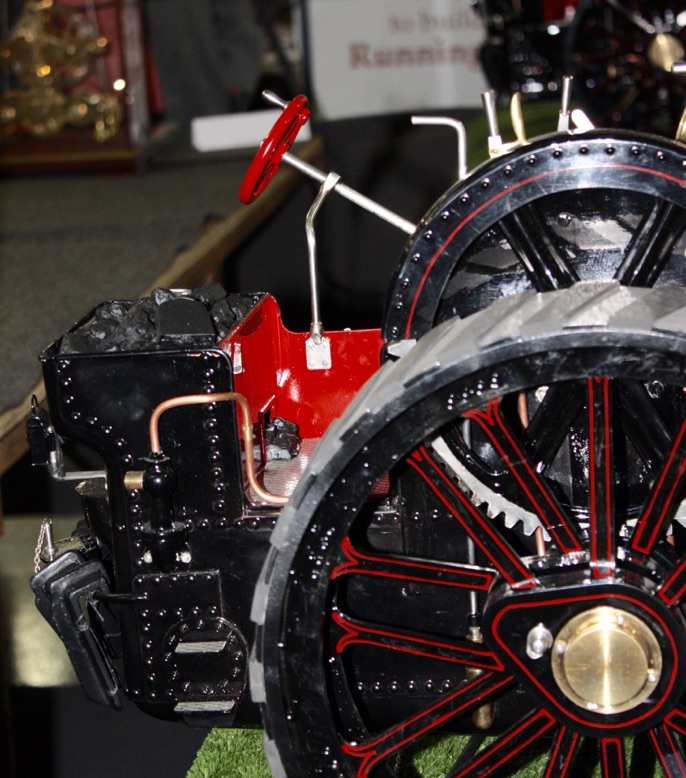
This excellent 1:6 scale model of the Fowler ploughing engines Sarah Jayne and Iris May with a six furrow balance plough was shown by Harry Williams at the 2015 Midlands Model Engineering Exhibition.


