THERE ARE a lot of articles written about the various methods for making spur gears but one method in particular, as used in the Sunderland Gear Planing Machine, has always had great appeal to me since it generates the required involute curve based on a very simple concept. The Sunderland Gear Planing Machine was designed and invented by Sam Sunderland of Keighley, York, circa 1910 who recognized that a simple rack would always mesh perfectly with a gear of the same specification. It was a small leap of imagination and design to realize that such a rack could thus be used as a cutter to machine a gear and in so doing generate a perfect involute curve.
It is also of some intrigue that the use of an involute curve should prove so successful and still used today. The involute curve, it seems, was identified by mathematicians many years before it was applied to gear design but like so many things it was a perfect solution to solve a problem the early engineers had ensuring gears would mesh together well and produce smooth and constant power delivery. The involute curve was not the only solution available but it was the one which enabled gears to be made in which the teeth remained in constant contact even allowing for some clearance on gear centres or even due to wear.
This was a crucial discovery as it meant that gears could be made to mesh together and produce rotational motion which was smooth and uniform, even if the gears had some clearance, which was of course necessary to prevent excessive wear, heat, noise and unnecessary friction. The other fascinating thing about the involute curve is that while it is relatively easy to describe it is not so easy to draw or machine thus many of the modern gear making processes use readymade form cutters.
In this context, form cutters I am referring mainly to, are for making gears in the home workshop which, of necessity, requires the availability of inexpensive cutters or a simple means of making them, such as the methods described by Ivan Law in his excellent book Gears and Gear Cutting.
A commercially available cutter is the Browne & Sharpe disc-type of involute gear cutters which are individually relatively inexpensive, depending on grade, but in order to cover a complete range of gear sizes one needs to purchase a set of eight cutters and these by definition provide only an approximation for certain sizes, albeit of little consequence.
If one considers this an acceptable way forward then costs soon start to dramatically escalate if a variety of gears with different sizes are to be made since each set of B & S cutters are specific to the gear specification of Pressure Angle (PA) and Diametral Pitch or Module (DP 0r Mod). A full set for a specific DP, Mod and PA requires eight cutters!
This brings me back to the Sunderland approach to making gears as this requires the use of a simple rack as a cutter and as this has no complicated curves it can be made very easily in the home workshop. With this thought I decided to design and build my interpretation of a Sunderland type of gear planing machine. At this stage the only information I had about the Sunderland was the basic operating process written down in a single paragraph.
Having never seen a real Sunderland machine I decided to design a new concept machine of model proportions such that it could sit on a bench top, contain no castings and be in a style sympathetic to the age in which the early machines and work along the lines described in those few words.
The model machine (now called the Involute Gear Profiling Machine) was to have an approximate foot-print 24 x 24in. and made from available stock steel plate and round bar. Other materials included a small amount of phosphor bronze for round bearings and a couple of ball bearings plus two commercially made Plummer Blocks for the drive shaft. The only other remaining needs were a set of gears so I decided to use some of my Myford ML7 set together with a few others that had seen better days as a base set (later, the machine could be used to replace these).
Designing the machine soon threw up a major problem relating to an inevitable lack of mass and size which help considerably to cope with intermittent planing cuts and absorb the severe cutting forces. So a few compromises had to be made in.
Another concern was that as many of the bearing surfaces would be relatively small they might easily be subject to wear and so bearings that have to cope with heavy loads have been designed as sliding die-blocks in a key-plate housing thus providing a much greater surface area and ability to resist wear. Finally, there was the problem of ensuring absolute synchronization of rotational and vertical movements which are fundamental and crucial to the Sunderland process and this evolved into the use of a ‘copy’ approach.
As the original Sunderland designer soon discovered while it was a perfect solution to use a cutter in the shape of a rack it would, of necessity, have to be short and thus the machine design would have to constantly reset the rack after each cycle. It was this continual resetting of the rack that eventually led to the Sunderland Gear Planer’s general demise though many are still in use today for ‘specials’.
In my interpretation of the Sunderland process the rack-cutter makes 25 equal incremental vertical movements (according to the gear DP) and for each of these the ‘copy’ gear (and copy-rack) rotates the gear blank an exact proportional amount. Once the rack-cutter has completed the 25 vertical increments it then has to lower to the start position but can only do so once the gear blank and copy gear move out of engagement to allow the rack-cutter to lower. Once lowered the gear blank and copy gear then re-engage to start another machining cycle.
Each cycle represents the machining of one or two teeth depending on DP requirements. All of the above movements happen automatically under the control of cams and require no operator intervention while the inclusion of a ‘copy’ method ensures accuracy and synchronization. All mechanisms are mechanical with no electronic assistance though there are two LEDs on the control plate, though these are not essential. A simple step-counter records progress.
The design and build of the model is not a copy of any known Sunderland machine and no reference was made to the original or current real Sunderland’s and the only thing in common is the operating process. However, I later found out that the method of interpretation differs considerably. The only other point of interest was to attempt to design the look of the machine to represent the Victorian style of engineering rather than the modern square functional but unappealing designs.
The model machine now finished and briefly tested is able to successfully and reliably make gears ranging from DP 18 to 48 or Module equivalent and having any desired pressure angle. The model currently uses a standard set of Myford DP 20, PA 14,5, gears to facilitate the copy aspect and by using a gear train arrangement the copy approach can derive gear sizes other than that made by a simple copy (i.e. a 30t gear can be derived from using a gear arrangement that does not comprise of a 30t gear).
The other significant design need was, using the standard Myford gear set, the ability to make gears having a different DP or Module and this can also be done (currently DP’s 24, 30, 34, 40 & 48). However, this can easily be changed to accommodate other sizes - DP or Module.
As mentioned earlier, due to the size constraints of the model some compromises have had to be made and in this respect the machine is primarily designed and equipped to generate an involute profile to gear teeth which have been pre-cut (straight sided tooth recesses using a suitably shaped fly-cutter). This pre-cutting is easily carried out in a milling machine by normal dividing methods to remove the bulk of redundant tooth-space material. The pre-cut gear-blanks are then transferred to the model and the machine then automatically proceeds (once the initial setting up has been done) to generate the required involute curve for all teeth without operator intervention.
The use of the Sunderland process ensures that the generated involute curve is accurate to the size of gear being made and since the gear blank has been pre-cut the wear to the rack-cutter and machine is negligible. A single rack-cutter is needed for each gear DP and PA and covers the full range of gear sizes. However, these are very easy to make in the milling machine using a fly-cutter and take approximately 1 hour to make and cost in the order of 50p each!
Total development cost of the model, including electric motor, materials and bought-in parts was around £100.
However, I was lucky to have access to some low cost scrap steel plate and all parts were made from two such rather big and heavy plates requiring the use of a good drilling machine and metal jig-saw plus a fair amount of effort! Machine covers are re-cycled stainless steel from a dish washer and some discarded shelving as indeed many other parts are made from bits in the scrap box.
A prodigious number of holes need to be drilled and tapped so it is definitely good practice to buy top quality hand taps covering M6 to M3 sizes of standard metric cap screws.
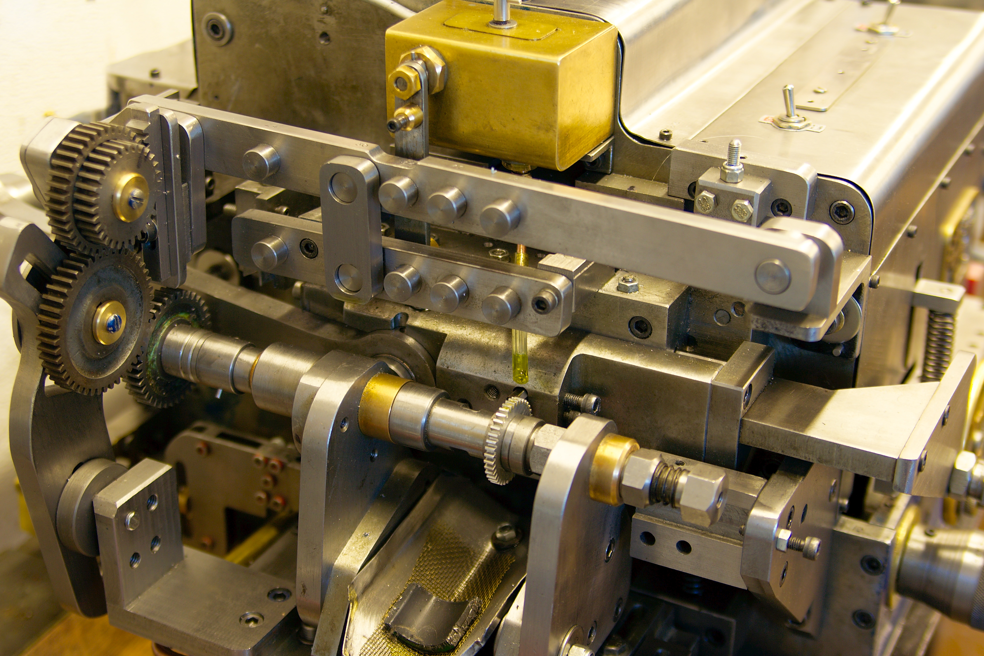
To accompany the model is a design and operator guide plus a build guide containing some 200 plus A4 drawings of parts and assembly stages (all in PDF format). The pictures in this article show the machine set up to use the Different Gear DP/Mod method in this instance to make a 38t gear of DP 30 and 20 degree PA.
More information can be found on my web site including a movie clip showing the first test run using the basic copy method.