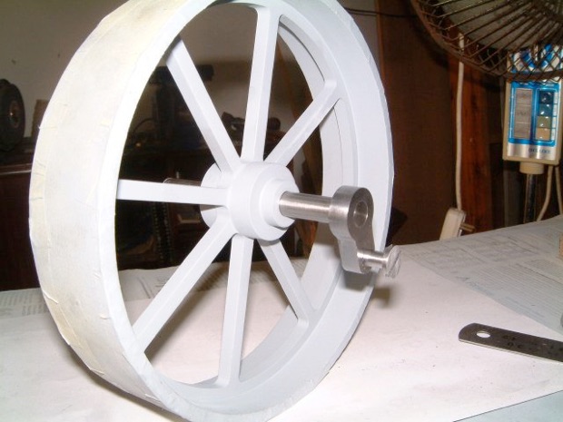
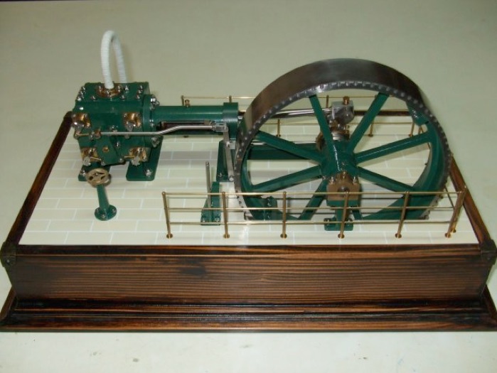
I wanted something simple to do after the flywheel and decided to do the crankshaft. The shaft itself was done from a piece of 10mm silver steel that I had. It fitted nicely in the flywheel so all I needed was to face it down to size.
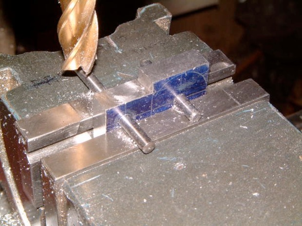
Next I did the crankshaft arm. A piece of mild steel was milled to size and two 4mm holes were drilled at the small and big end.
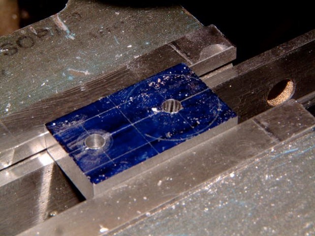
Some more milling....
Then it was bolted to a piece of aluminium plate and with the rotary table the radius of the small end was done.
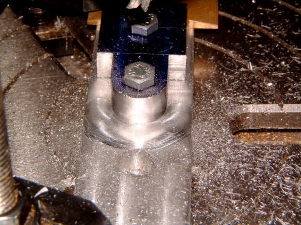
And then the big end.
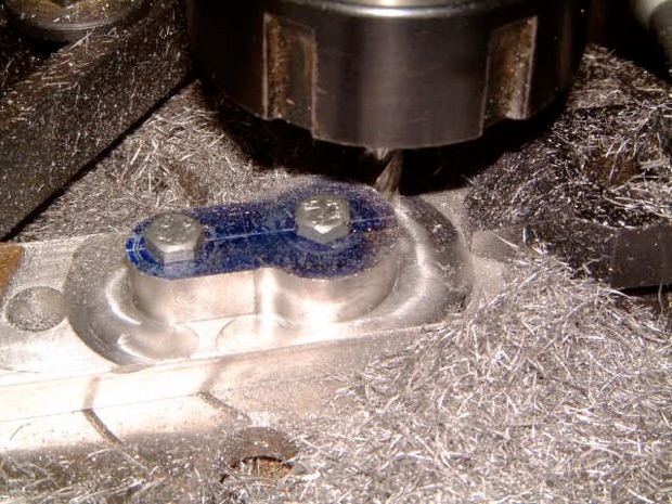
And here it is still bolted to the plate.
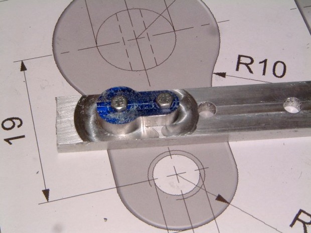
The hole at the small end was tapped 5mm and the hole at the big end was widened to 9.9mm. Next, the crankpin was turned and the three items shown below.
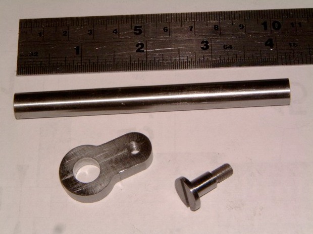
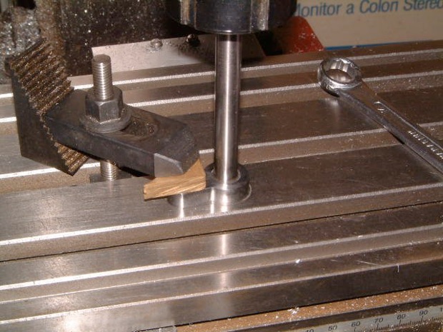
Cleaned up the arm and crankpin and then pressed the crankshaft into the arm. I wanted to make sure that the shaft was perpendicular to the arm so started the pressing operation on the mill.
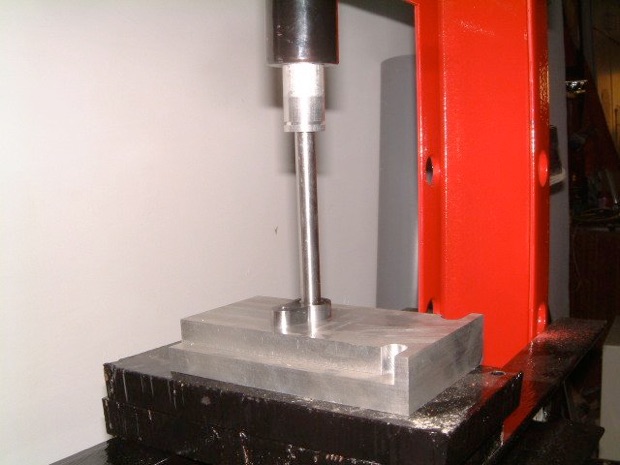
When it started to get hard to continue pressing, I transferred the assembly to the hydraulic press and continued until the shaft became flush with the arm.
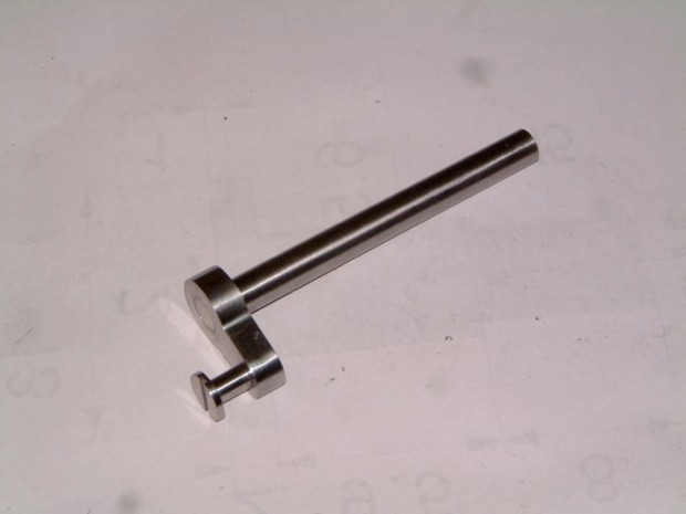
A shot of the completed crankshaft
And fitted to the flywheel.