MAKING A HAMMER
By Charles Marks


MAKING A HAMMER
By Charles Marks

My model engineering ‘wish list’ of things I wanted to make started with 15 items. Latest two items completed were:
• Machinist Hammer - a Hemingway kit – I just like the look of it and I am fed up trying to judge a ‘gnat’s whisker’ with my ball pein hammer!
• Offset Centre (Hemingway) (or ‘set-over centre’) so that I can turn the taper on the handle of the machinist hammer without upsetting the tailstock setting.
Although I really wanted the machinist hammer I had to make the offset centre first.
The offset centre is a straightforward piece of work made interesting by offering an opportunity to use both milling machine and the lathe. Its purpose is to allow you to turn tapers on work pieces using the lathe. This is done by turning between centres and is achieved by offsetting the tailstock centre by an amount that produces the required taper on the work piece. This is, I am reliably informed, a simple matter of geometry as follows:
S=Tan(X0) x L
Where:
S = the offset of the tailstock
X0= the half angle required, and,
L = the effective length of our job between centres.
So to get a taper with an included angle of 60 on a 5” shaft, we will need an offset of Tan(30)x5 = (0.0524 x 5)= 0.262”. (Simples!!!)
Those of you with a lathe will no doubt shriek in horror at having to offset the tailstock by any amount. This is because getting the tailstock perfectly in line with the mandrel (concentricity) is vital for accurate turning. It normally takes me at least 30 minutes of fiddling around with a parallel test bar, a dial test indicator (DTI) and sundry screwdrivers to achieve the best alignment (perfection eludes me). All this work is a real disincentive to try any taper turning but this is where the offset centre attachment saves the day by allowing you to fit into the tailstock a device which is adjusted to get the offset but leaves the tailstock unchanged.
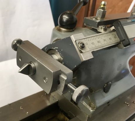
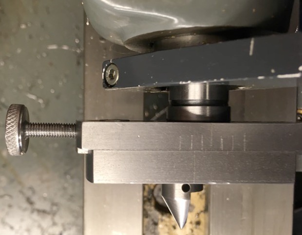
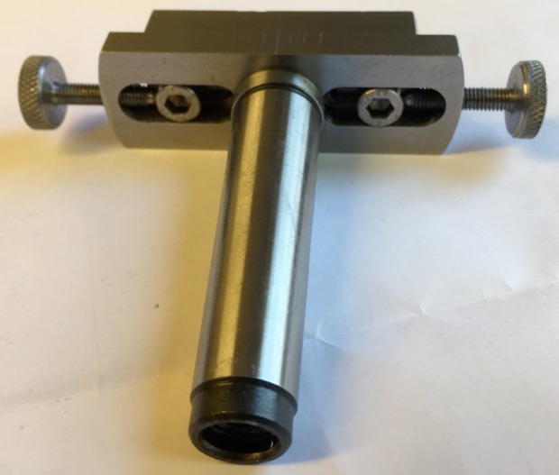
Photo 3 (above) shows the locking screws which are loosened and the offset made by means of the opposed thumbwheel adjusting screws and then the locking screws are retightened. The photos show graduation or fiduciary marks designed to help measure the offset. In practice I made a direct measurement of the offset using a parallel test bar and DTI positioned along the test bar to match the position of the taper on the work piece. You do need to ensure the device is truly horizontal/parallel with the lather bed. It is also worth noting that this device can do nothing to correct any vertical misalignment of the tailstock centre line with that of the mandrel.
All in all a very good kit from Hemingway and a useful device, if one that will be used only occasionally.
Having made the offset centre I was then able to make the machinist hammer. Again this was made from a Hemingway kit and produces a
tool which I think is aesthetically pleasing and very useful. At first sight it looks almost ridiculously simple but the handle taper, the head fixing and the bimetal head provide considerable interest for the maker. (See photos 4 and 5 below).
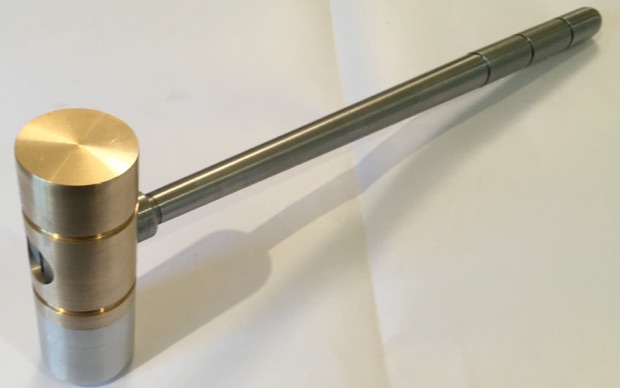
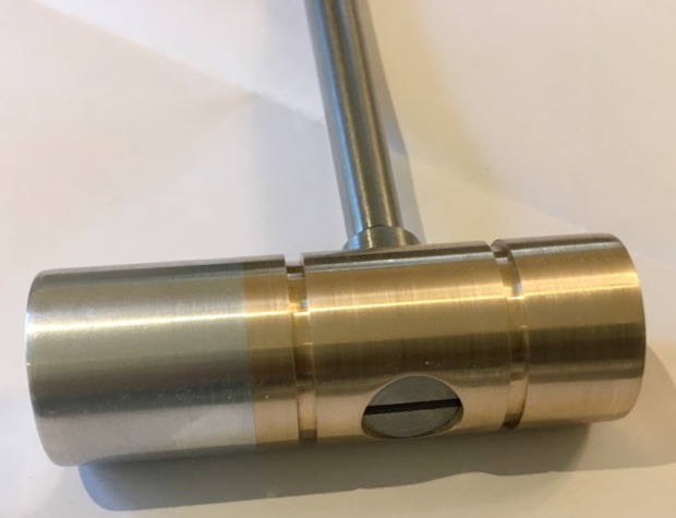
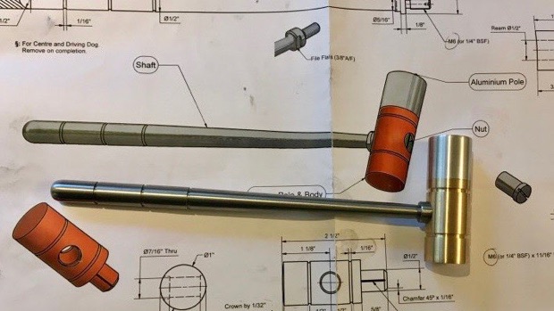
Photo 6 (below) shows the finished hammer with part of the single sheet drawing that comes with this kit. The drawing will answer any queries you may have about the hammer’s construction.






Modelengineeringwebsite.com
the only free and the only weekly magazine for model engineers.
Editor: David Carpenter