...Continued from part seven
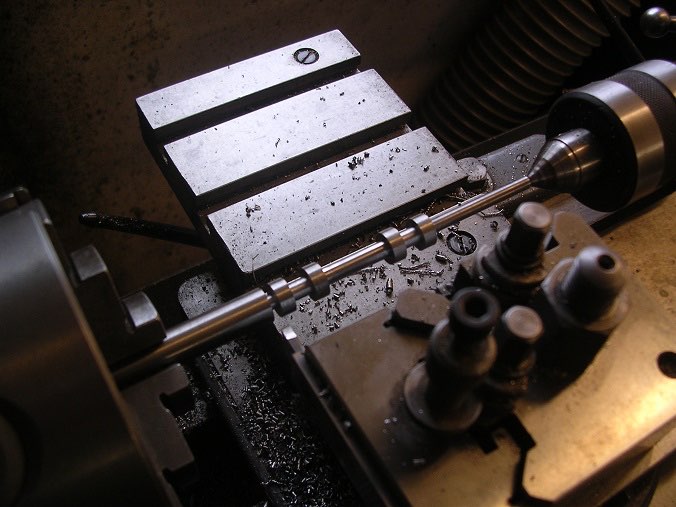
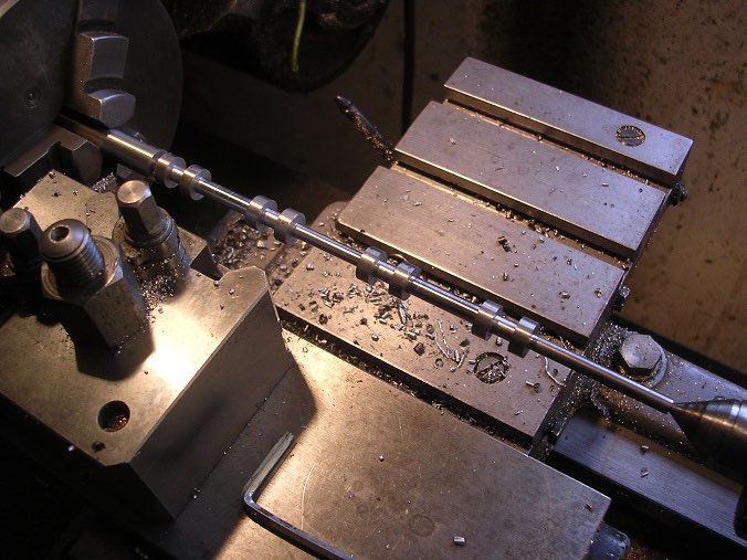
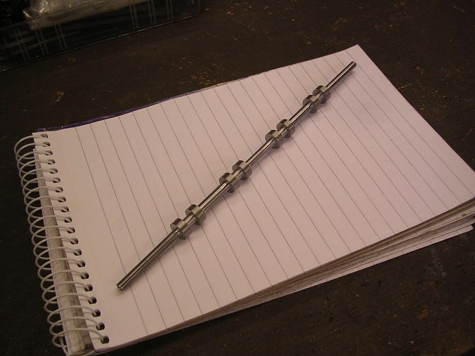
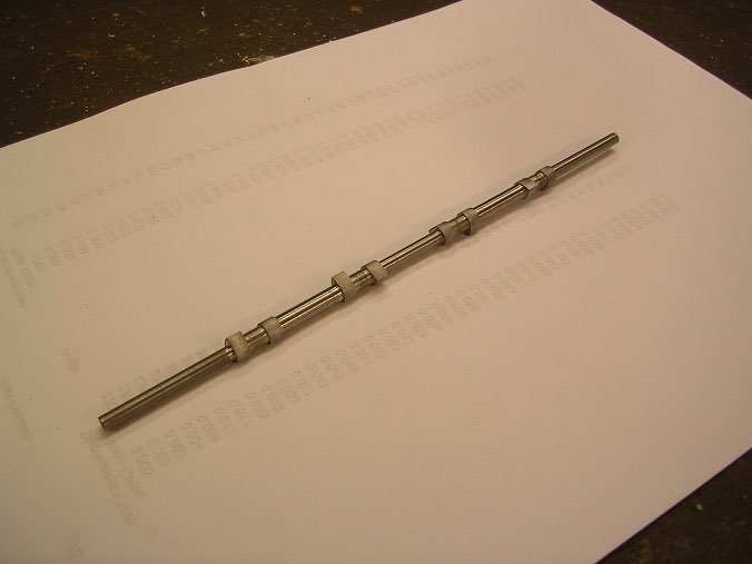
Next, turning the camshaft blank.
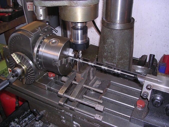
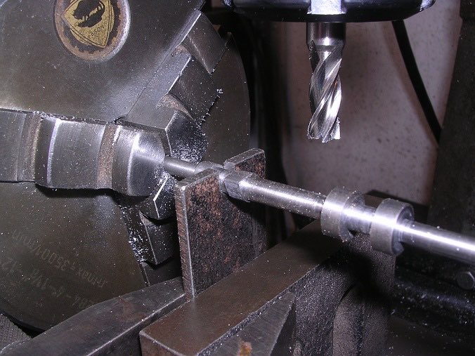
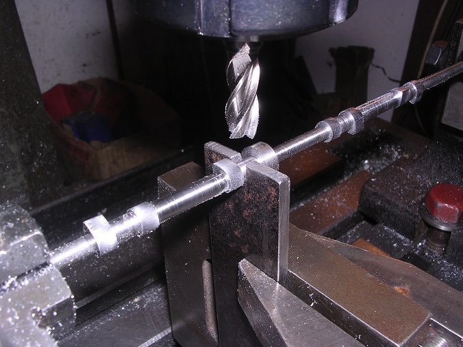
To machine the cams, I set up with the dividing head and a steady made from a piece of plate.
It all went quite well in the end although there were 130 cuts per cam and eight cams so it did get a bit tedious. I don't think the mill has run for so long in many a year. The result is satisfactory but not perfect as the base circles vary a bit in diameter. I put this down to my steady not properly supporting the shaft so the next time I cut cams, I will make a proper one.
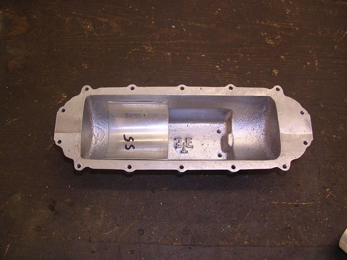
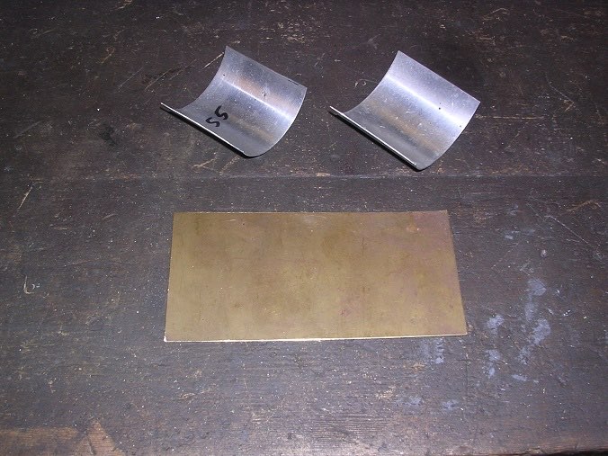
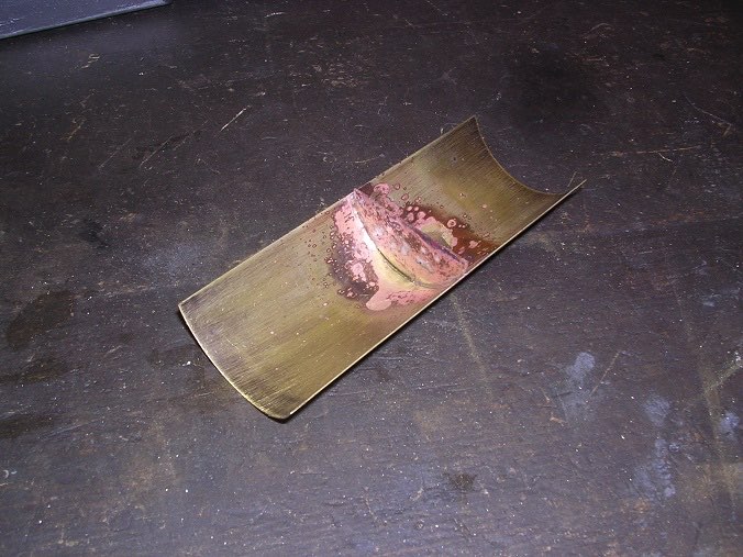
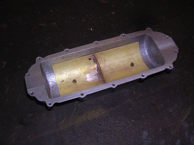
I made up the tray for the bottom of the sump so that the big end dippers have a profile to follow. I started off by trying a piece of aluminium to get the length right.
Once that was confirmed, I cut my brass.
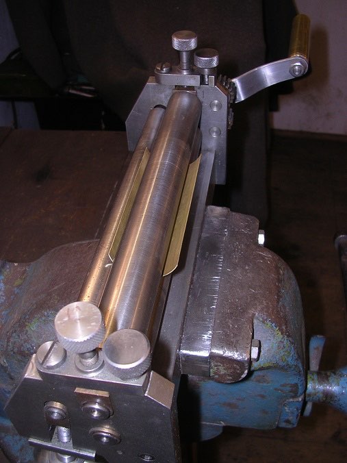
It is very thin so I could easily have curved it by hand but it just so happens that I made George Thomas' bending rolls some years ago so it was a good excuse to get them out and blow the dust off!
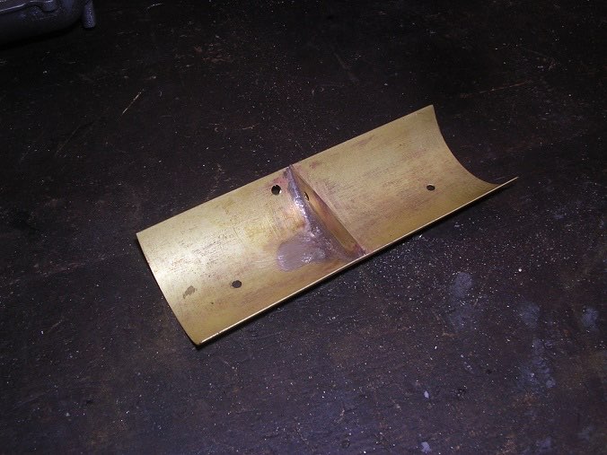
I drilled a level hole and overflow hole as shown in the drawing and also screwed it into the bottom of the sump.
It all looks very nice but it is a slightly odd arrangement. The divider between the two halves of the crank case means that I could fill one end without filling the other. Also, there is no way of telling how much oil is in the engine. It needs a dipstick or level plug.
Continued in part nine