


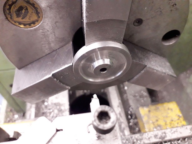
I was able to keep the 21/42 tooth count on the timing gears by using MOD 0.8 which gave a suitable PCD distance. So first job was to machine the blanks. This is the larger gear that has had the faces recessed.
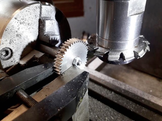
Unfortunately, when cutting the teeth on this one the 4mm central hole was not up to holding it still and the gear crept on the arbor. It was also quite chattery. So another blank was cut but this time left flat faced and an angle plate placed against the blank so it could also be clamped to that with a toolmaker’s clamp and all went well. I also used 32DP cutters but cut to the MOD 0.8 dimensions as there is so little difference between the two and I had the 32DP cutters.
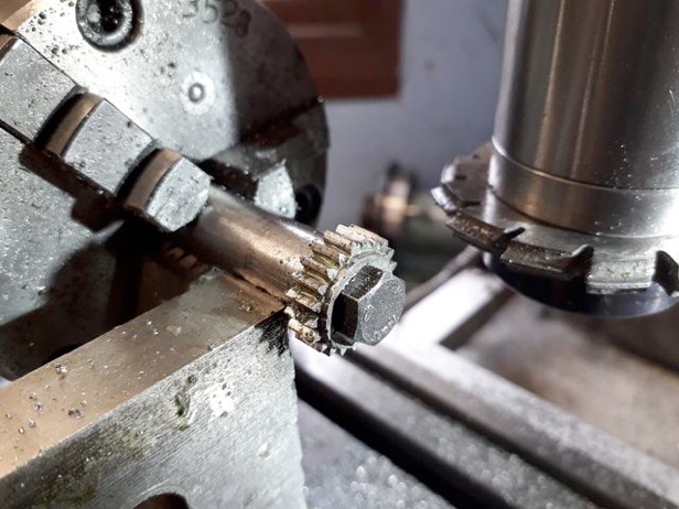
The smaller 21T gear was not a problem having a 10mm hole though I did butt the angle plate up against the arbor to stop any deflection.
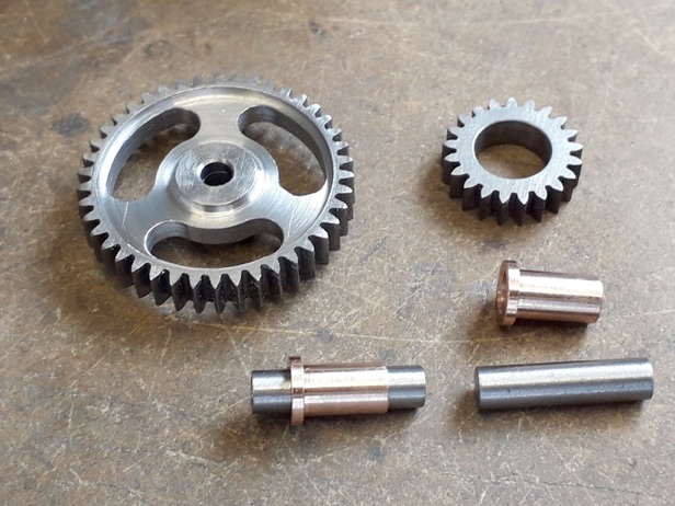
The large gear was then recessed and some weight reducing slots added more for looks than performance. Also in the photo are the two silver steel (drill rod) tappets and some bronze guides that I decided to include rather than having them run in the plain crankcase holes as shown on the original design.
The crankcases were then held in the mill vice and, with a 10mm dia carbide cutter shank in the main bearings to support the small gear and the large gear mounted on the camshaft blank held in a collet, the backlash was set and the DRO zeroed so that the holes for the camshaft bearings could be reamed in the exact position required.
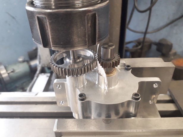
All seemed to run smoothly enough.
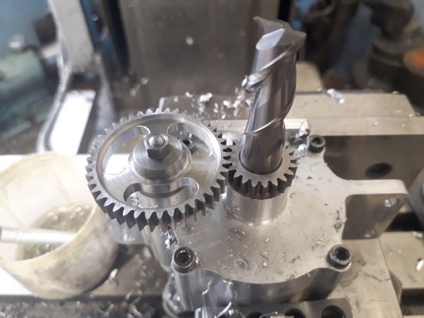
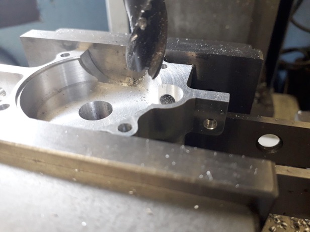
With the holes done I split the crankcase halves so that the hole could be located on the mill and a recess opened up to give clearance for the cams.
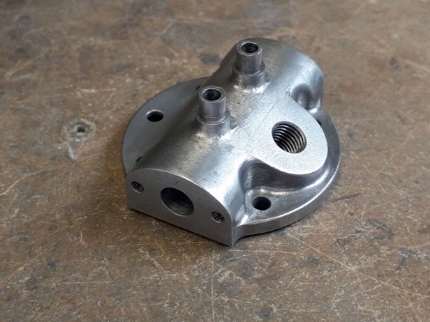
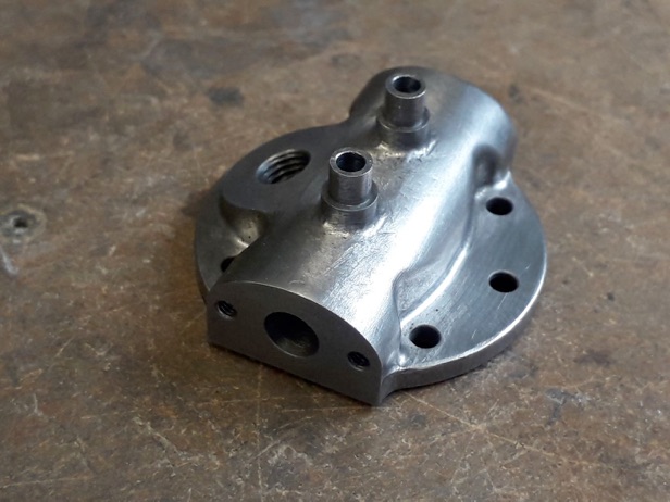
I made a couple of changes to the cylinder head, the most obvious is a separate post for the rockers to pivot on rather than one cast integral to the head. The other difference was to omit the way that the valve guide extends into the valve chambers and to retain the length of guide these were extended further above the head which also meant I could machine a step to help locate the valve spring.
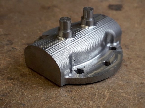
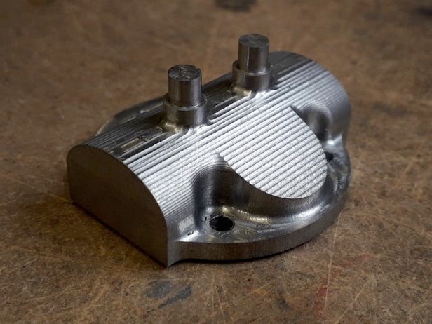
I started by facing some cast iron bar in the lathe and forming a shallow spigot to locate in the bore. Then over to the mill and two holes were drilled and tapped into the valve cavities which allowed me to screw the head to a block that could easily be held in the CNC mill's vice.
I could have set a finer step down on the contouring cuts which would have needed a bit less finishing but was happy to need a bit more filing as that would give a bit more variance that gives a more ‘cast’ look.
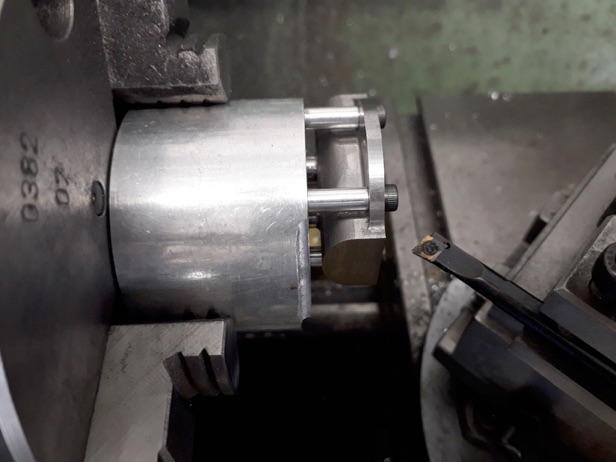
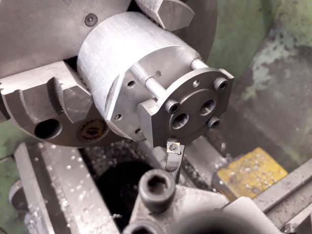
I always prefer to bore my valve cavities, ream the guides and machine the seats with a boring bar all at one setting.This needs very little lapping and results in a good sealing valve. To do this a simple jig was made up consisting of a bit of bar with 4 offset tapped holes and 4 standoffs, it was then just a case of screwing the head to this to do one valve and then taking it off, rotating 180deg and screwing back on to do the other.
It was then over to the manual mill to drill the exhaust and inlet passages as well as adding the M2.5 tapped holes for the carb and exhaust flanges.
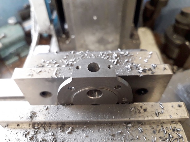
An angle gauge was used to set the head in the vice so that the spark plug face could be skimmed and the 1/4" x 32 threaded hole for the Rimfire plug added.
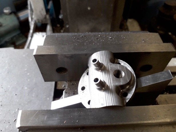
The last thing to do was remove the contour lines left by the CNC with the aid of needle files and that was the head complete.
Part one here Part two Part three Part four Part five Part six Part seven