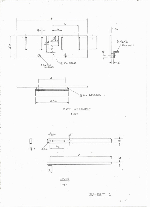
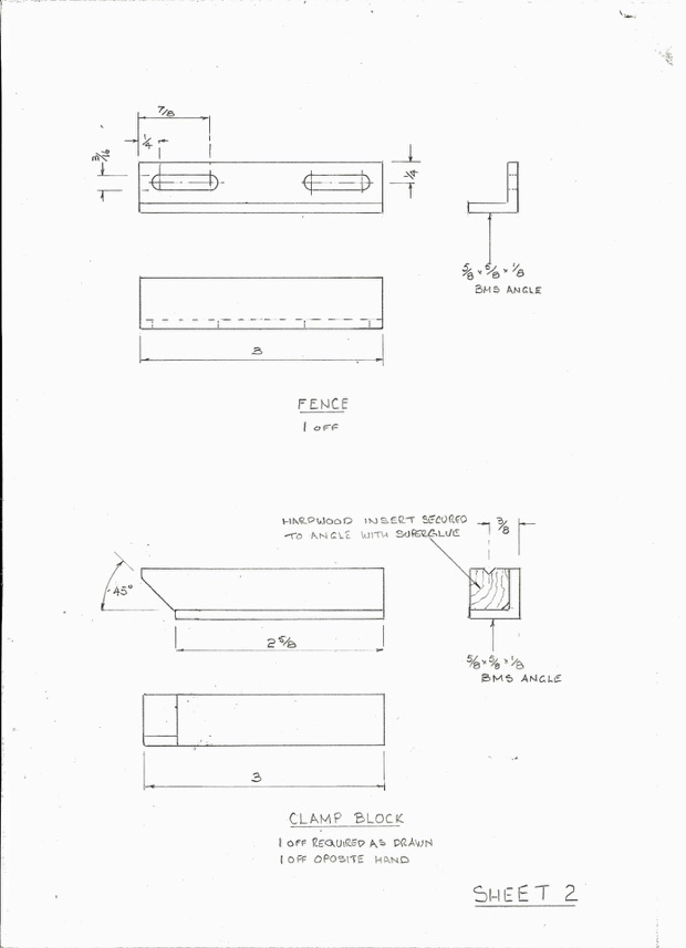
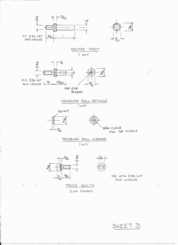
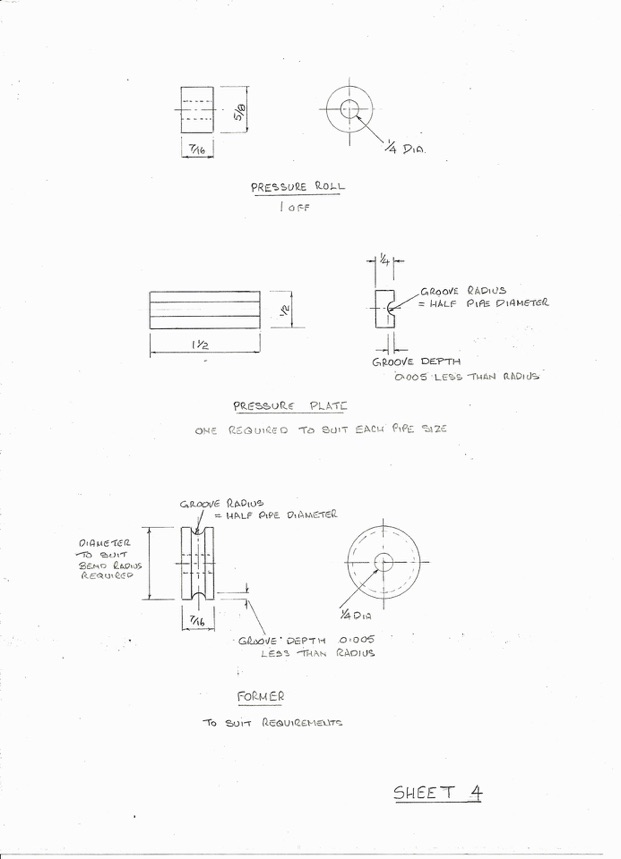
In my article on Pipes and Pipework I described a pipe bending machine which I employ in my own workshop. Following publication of the article I received a request for further details of the device and our editor suggested that I should write up some notes on its design and construction.
Design
Let me say right away that the design is not mine! My own machine was built to a design published in a magazine many years ago. Unfortunately, I do not remember the title of the magazine concerned and have lost my original copy. I thought it was Model Engineer but can find no record of the design in that journals archives. If the original designer of the machine should read these notes I shall be delighted if he will make himself known and take credit for his ideas!
The basic principles involved in the machine are well established and are employed by many full size pipe bending machines. The drawings herewith have been prepared from my own machine and incorporate one very important change from the original design. As originally published the design employed a pressure roll grooved in the same way as the formers and bearing directly on the pipe.
While this arrangement works the grooved pressure roll does not constrain the circular section of the pipe well enough to avoid some distortion of the pipe section on ‘tight’ bends and an unsightly ‘kink’ at the outside of the finished end of the bend. The use of a grooved pressure plate constrains the pipe section much more effectively and results in a very smooth bend with no distortion of the pipe section, even with very tight bends. Having said that, I have come across one or two situations where the bending configuration required allowed insufficient space for the pressure plate to be used and I have resorted to the original concept of a grooved pressure roll.
Before leaving the subject of drawings perhaps I should apologize for not moving into the twenty first (or even the twentieth, some may say) century. My drawings are all produced the old fashioned way on a drawing board with a pencil and paper. My computer does not run to CAD software and in any case, I recon I can draw more quickly with a pencil than I can on a computer. When I was working in industry I always developed new ideas and designs on paper before moving on to the computer. The drawings presented here are therefore scanned from my hand drawn images.
My own machine was made with formers to accommodate pipes of 1/8”, 5/32”, 3/16”, 1/4" and 5/16” diameter.This has satisfied most of my needs building 5” gauge locomotives and some stationary engines. The formers were made for a range of bend radii with a minimum radius of twice pipe diameter.
Construction
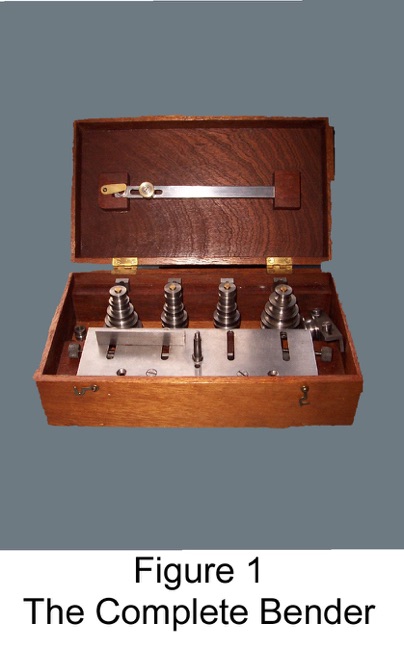
The exceptions are the pipe formers and the pressure plates. These are key components in achieving satisfactory results.The blanks for the formers are simple turning jobs with the diameter of the blank being made equal to twice the radius of the centre line of the pipe bend required.
You can either make a range of formers for different pipe sizes and bend radii when you make the rest of the machine or make them as occasion demands. I made a range of formers as I made the machine – it is a bit of a fag to have to stop in the middle of a plumbing job and set up to make a former.
Operation
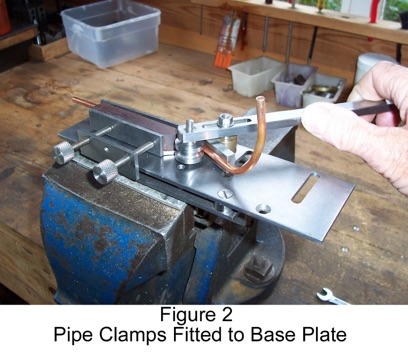
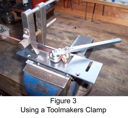
I have not produced a general arrangement or assembly drawing because in practice the components are assembled to suit the pipe configuration being manipulated. The original design incorporated clamping screws attached to the edge of the base plate as shown in Fig.2. Although I fitted the arrangement to my own bender I found that it is more trouble than it is worth and I invariably use a toolmakers clamp as shown in Fig. 3.
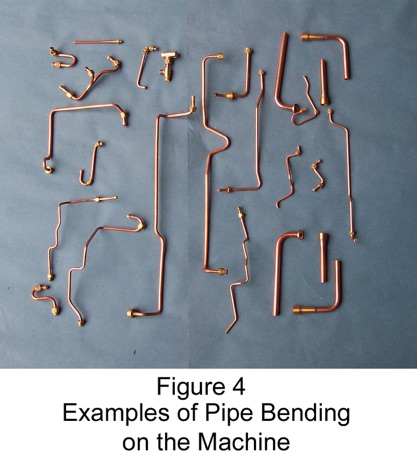
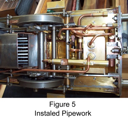
If complex configurations of pipe work are being produced a little ingenuity must be used in order to secure the work to the fence in a suitable attitude, but quite complex formations can be produced when necessary. Fig.4 shows a batch of pipes produced for my most recent project and Fig. 5 shows some of these pipes in situ on the locomotive.
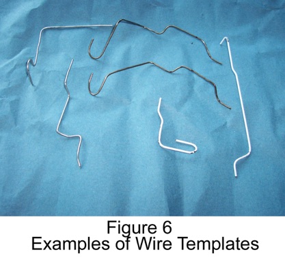
Before bending any pipe I always make up a wire template – old wire coat hangers provide a good source of suitable material. A selection of typical templates is shown in Fig. 6. Copper pipe is expensive and mistakes are very difficult to rectify neatly. Better to spend time (and coat hangers) getting it right first time. The original design specified two fence angles. I have only ever found the need for one, however, and have only specified one on the drawings.