CREATING A CARBURETTOR -2-
By Graham Meek

CREATING A CARBURETTOR -2-
By Graham Meek



Continued from part one
Click on drawings to download.
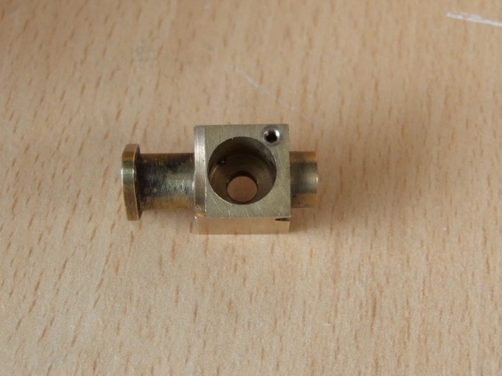
At first glance the spray bar or jet assembly body looks to be a complicated piece of machining, but if the job is approach in the right way it is not too difficult. A piece of brass was first milled to the shape in the form of a cross; the overall dimensions and width can be finished to size. If care is taken at the cross machining stage to get the arms of the cross close to their finished diameter sizes then when the work is held in the 4-Jawed chuck these faces can be used to clock the work to ensure the correct position is attained.
The first portion to be machined was the actual spray bar that sits in the Venturi along with the O-ring groove that seals the spray bar and throttle body interface. The 1.1mm diameter hole in the centre of the spray bar is only drilled about 9.5mm deep at this stage. A short stub of brass or aluminium now needs to be made that will protect this machined portion when it is gripped in the 4-Jaw in order to machine the jet adjusting screw thread.
It will pay to make this slave piece a good fit on the spray bar portion and to clean up the outside diameter of the slave piece at the same setting, as later it will need to be slit so as to act as a collet. Therefore, gripping on what will be the submerged portion of the jet and across the spray bar protector slave piece and the as yet unmachined air bleed portion, the needle valve adjustment thread is the next item to be machined along with the O-ring groove, the 1.6mm drilled hole can be machined and the 1.0mm diameter hole that will form the jet orifice. I have found it better to drill this hole prior to the fuel inlet hole, as the tendency for the drill to break when connecting with the fuel inlet hole is too great.
I would urge you to screwcut the M3.5 thread in order to maintain absolute concentricity with the needle valve bore, a slave piece of brass is first drilled and tapped 3.5mm by 0.6mm pitch to act as a gauge for sizing the thread. This is a handy tap to have as most UK sockets these days use this screw thread for attaching the pattress plates, I have lost count of the number of times I have used this tap to clear out a damaged thread at my daughters left by the previous occupant.
The last operation is to slit the previously made slave piece so that the work can be gripped in the 3Jawed chuck and to machine the extra air hole, this needs to be a flat bottomed hole as there is a 1.2mm hole breaking into this hole from the outside diameter to allow the air from outside to enter the engine. I used tailstock support with a running centre in order to machine the outside 5mm diameter portion after all the interrupted cut from the initially milled portion could rip the job out of the collet, the centre stops this from happening.
The 1.1mm drilled hole that connects with the spray bar is best done after the flat bottomed hole has been produced and I initially used a 1mm slot drill for this operation to ensure the hole went in on the true centreline finally opening up the hole with the 1.1mm drill. Beware that this drill is going to be breaking into the 1.6mm needle valve bore so proceed with caution, if you meet with the 1.1mm hole from the spray bar without any misalignment then well done, if there is a slight error then it does not really detract from the operation of the carburettor.
The second tap was used to start the M3.5 thread as the taper tap was bottoming in the hole before it even started to cut, both the second and plug taps for this thread needed the male centre ground off to allow the thread to extend to the bottom of the hole, the plug tap was ground such that the first full thread was adjacent the end of the tap. All that remains to be done is to coordinate drill for the single attachment capscrew and to drill and ream for the fuel inlet hole, which it will be found easier to do if the location for the hole is first spot faced with a slot drill before centring with a BS1 centre drill. Not forgetting the 1.2mm air bleed hole into the extra air screw, starting this hole can be difficult as it is that close to the jet body that the body of a normal centre drill will not allow one to get close enough to the jet body.
There are two options, one is to grind down the body of a BS1 centre drill, this is fine if you have a cutter or tool post grinder, the other is to raid the sewing box for a large needle, using this needle held in an Eclipse style collet chuck at the correct coordinates a small centre pop is made in the jet body to start the drill, be sure to return the needle but if you have damaged the point I would suggest a new packet of needles which could well earn you some valuable “Brownie” points. The fuel inlet tube was soft soldered into position and after applying some flux a piece of Multicore solder was cut off and placed on the joint, the amount needed is very small and produces a nice fillet around the joint when heated with a small butane torch, similar to those used for caramelising the tops of desserts.
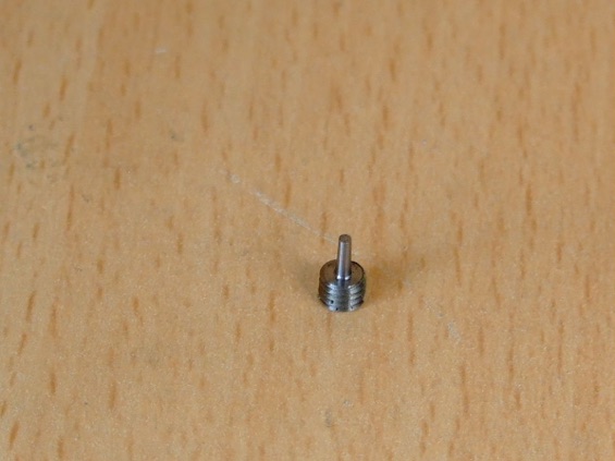
The extra air bleed screw was made from EN1A Pb, the screw thread as with the needle adjustment screw was screwcut to ensure absolute concentricity, plus it was made a very good fit in the spray bar body, the last thing needed is for vibration to disturb this setting. Once the thread is screwcut the tapered portion is the next feature to be machined, if a parallel portion is machined 1.2mm diameter by 3.5mm long initially then with a felt tip marker this portion is then covered in marking ink. Adjust the topslide to produce a 2º taper, i.e. 4º inclusive taper, now using the topslide and cross slide feed screws simultaneously just touch on the extreme corner of the 1.2mm diameter, this should show as a bright ring around the extreme end of the diameter. Zero the cross slide micrometer collar, from this point to the intersection of the taper with the threaded portion is only a very small cut, 0.1mm (0.004”approx), so with an initial cut of 0.05mm this should bring the runout of the taper half way along the diameter, if this is the case then a further 0.05mm cut should take the taper almost to the intersection point and a further 0.025mm cut should bring the diameter at the small end to 0.95mm. It goes without saying that the turning tool for this operation wants to be well honed and with only a very small radius on the corner, otherwise the orifice in the jet body will be blanked off prematurely by the radius left in the corner.
The slot for the screwdriver blade was machined in the extra air screw by making a small holding fixture that mimicked the hole in the spray bar body, that is there was a 1.5mm diameter hole to clear the tapered portion of the screw and an M3.5 thread which is flat bottomed. Having semi parted-off the extra air bleed screw it was then screwed into the slave body using the bar stock for purchase until it was tight. In my case the semi parted portion sheared when the screw was fully home, but I am sure in the case where it does not shear, that if the parent stock were to be rocked to and fro the metal left from the semi paring off would fail under fatigue. The slave body is then gripped in the machine vice or the indexing unit to machine the slot with a small slitting saw, the width off the slitting saw being sufficient to removing the pip that was left from the semi parting off operation, then use a screwdriver to remove the finished screw from the holder.
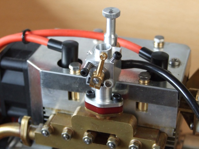
After using this method for the first prototype I decided that trying to get a screwdriver aligned with a vibrating little engine is not the easiest thing to achieve, to this end I ground up a 1.5mm hexagon broach from an old broken end mill and broached a hole in a new extra air bleed screw, using the same technique as above for the slitting operation, a photograph shows this feature, now one Allen key can be used to adjust any adjustment. In addition the short arm of the Allen key is a very good indicator of where the particular adjustment screw was prior to an adjustment just in case there is a need to take one step back after making a wrong adjustment.
From the photograph you will see that the needle valve adjuster is machined from aluminium this allows for a fine crisp knurl to be produced without too much difficulty. All work can be carried out at one setting and it would pay to either bore the 5,1mm diameter or use a D-bit to produce a nice smooth surface for the O-ring to slide over.
The reader can if he or she chooses turn up a PTFE ring in place of the O-ring, if a diagonal slit is produced with a sharp utility knife it can be slid along the M3.5 thread into the groove and gently pushed into place. If the outside diameter was made slightly larger than the 5.1mm diameter say 5.15mm then this will give a suitable amount of nip to ensure an airtight seal. This technique will also work for the seal for the jet body to throttle body; I used this when doing the initial modification just to see if it would work before I purchased the silicone O-rings.
After paring off the work it was lightly held in the 3-Jawed chuck with a drill shank in the O-ring bore to prevent the jaws from crushing this portion and with one wrap of note paper around the outside to prevent the jaws damaging the work when satisfied all is secure and the work is running true the parted off face is cleaned up with some light cuts, overall length is not critical.
As can be seen from the photographs the remaining adjustments are all made with standard M2 by 12mm long capscrews. Both these capscrews however need some additional work done on the ends of them. To accurately achieve this I usually turn up a small “Top Hat” shaped tapped bush, the capscrew is inserted into the top of the Hat and locked onto this face, this end then goes into the chuck jaws and the Brim of the hat butts up against the face of the jaws, which helps to keep everything square as well as forming a reference point should there be several capscrews to modify. In the case of what I call the slow running air bleed screw this needs turning down to 1.6mm diameter by about 2.5mm long after first facing the end off.
The second capscrew for the throttle slow running adjustment needs to be faced off then turned down to 1.5mm diameter by about 1mm long, and then the turned spigot needs a hemispherical end produced to allow for the angular variation of the throttle. Purists can make a radius tool for the job, which I find is never a bad thing as these tools will always come in for other work, or if the constructor is adept at using the Graver then the radius can be formed freehand.
The throttle lever in all cases on my Seagull is to Westbury’s design and a special form tool was made to form the ball end of the lever, but the choice of lever may differ with each constructor especially if the engine for which the carburettor is being made is for a Radio Controlled model whereby additional linkage points may be needed or perhaps a commercial lever is being used. The original Curtis drawing had a tapped hole in the throttle barrel for attaching the lever; this tapped hole is shown in the General Assembly (GA) cross sections. As regards the assembly there is very little that needs any special description other than the setting of the full throttle stop screw, if the length is judged correctly then with the head of the screw tightly against the carburettor body and peering down the throttle bore with the throttle barrel in place one should see an uninterrupted passage.
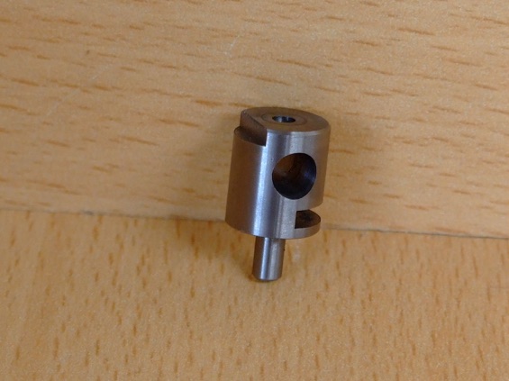
If the throttle stop has gone in too far then a small Delrin or Nylon washer under the screw head will correct the problem. If on the other hand the throttle is opening too far because the screw is not quite long enough then a slight spot face around the screw hole to clear the screw head will correct this type of defect. I did lubricate the O-ring seals with some Silicone grease just to assist assembly, with just a little low melting point graphite loaded grease on the needle adjustment thread.
The needle was inserted into the jet tube after first screwing on the jet adjuster as far as it would go, using a scriber with the needle gently pressed in as far as it will go mark where it needs to be cut off, once this has been done degrease the needle and the needle adjuster hole and assemble with Loctite 603. This then ensures that all is in perfect alignment and that when the needle adjuster is fully home no damage to the jet seat can occur, the rest of the assembly being pretty straightforward. If you prefer to solder your jet needles in then the needle valve adjuster will need to be made from brass and the needle valve left oversize on length to allow for a small fillet of solder.
After mounting the assembled carburettor on the engine and connecting the fuel supply, the engine was primed with the throttle blocked and the jet adjustment opened about 1 to 2 turns, the idle screw is adjusted to give about 1/3 rd†open throttle, which is then opened manually using the throttle lever to about half throttle. The extra air bleed screw at this stage is flush with the end of the jet body and the slow running air bleed screw wide open.
Once the engine is running slowly close the throttle to the throttle stop, it may be found that the engine starts to “hunt” due to the mixture being too rich, slowly close the jet adjustment screw, but only until the engine settles to a steady beat. Once the engine is warm the throttle can be closed a little at a time with the throttle stop screw while at the same time screwing in the slow running air bleed screw and the extra air bleed screw. Using the short arm of the Allen key it is quite easy to judge 30º increments at a time, slowly but surely while continuing to adjust all three screws and the mixture screw from time to time the engine will settle into a gentle tick over.
When the throttle is opened for the first time it may be found that the engine will or has a tendency to stall or is sluggish to pickup, this usually means the main jet is too weak, open the throttle wide if the engine is still running and set the main jet to get a smooth power output but with no black exhaust smoke as this means it is definitely too rich. Gently close the throttle, there may be a tendency for the engine to cut out again, if so open or close the extra air screw slightly which should make it easier to close the throttle further, which may mean another further adjustment to the extra air screw, as one gets nearer to the idle speed then it may mean tweaking the extra air and the slow running bleed screw together. When the adjustments get to this stage it is best to make fine adjustments, 30º increments would be far too excessive.
As the reader is probably familiar with petrol engines then he or she will appreciate that while the above approach worked on the Seagull it will probably require a somewhat different approach to another engine. It was, however, possible to have the Seagull fully tuned inside 15 minutes and I now have a very docile engine that sounds just like a Triumph twin when idling or at full bore and the pickup between the two positions is really smooth. It is interesting to note that the extra air bleed screw is one turn from the fully closed position, this equates to a hole 0.28mm diameter and the hole in the original carburettor for Seagull was a number 60 or 1.02mm diameter, so it would seem my theory on this hole being too large was true. As the smallest drill easily obtainable for the home machinist is a number 80 this too would be a little on the large side, therefore a new carburettor body to Westbury’s original design but with a number 80 drilled hole across the spray bar would I feel a worthwhile exercise.
All in all I have found the whole process very fascinating and I have learned a great deal along the way, I do also wonder if some of the additives that have been removed over the years from the petrol obtainable from the pump when compared to what was obtainable in Westbury’s day have in fact made it more difficult to tune the older style carburettors. No doubt someone with a better knowledge of chemistry than myself can answer this one way or the other, chemistry was never my strong point. I do hope you have enjoyed the evolution of a carburettor, which in actual terms on and off has taken about six years to complete with the modifications to my side valve design still ongoing, but then time does fly when you are having fun.

MEWS IS SPONSORED BY - CHRONOS - PAULTHECAD.CO.UK - ECCENTRIC ENGINEERING - WARCO - BRISTOL EXHIBITION - HARROGATE EXHIBITION - MERIDIENNE EXHIBITIONS - CAMDEN MINIATURE STEAM - TRANSWAVE CONVERTERS - CHERRY’S MODEL ENGINES -
Model Engineering Website is edited by David Carpenter