MACHINING ‘CASTINGS’ FROM SOLID
Part three by Mike Sayers


MACHINING ‘CASTINGS’ FROM SOLID
Part three by Mike Sayers

Component 3 ~ Manifold from the 1929 Bentley Birkin 4½ litre supercharged engine
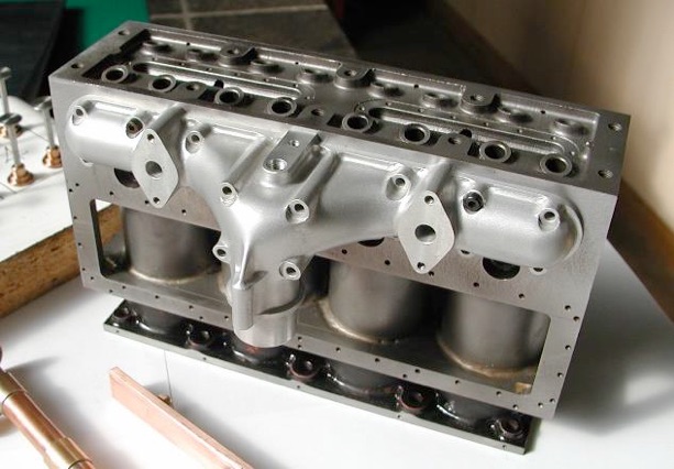
It can be seen in the photo that the centres of rotation have been marked on the machined excess end blocks. Again, the component’s machined back face is set up against a parallel.
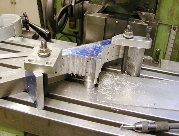
The centre datum can be established with a sharp pointed laser, for example and then all hole datums can then be coordinated from that, without the need for ‘marking out’.
All of this requires a lot of work with the drawings beforehand determining coordinates from the centre line datum.
The original Bentley archive drawings were all dimensioned the old-fashioned way. All the drawings had to be redrawn and dimensioned from a machining origin. If you start out correctly, you will finish correctly.

The stud bosses are quite long, so it was decided to use ‘guide discs’ at the end of each boss, 10 thou larger than the boss circumference. The cutter then passes along each boss guided by the disc at the end, which is similar to using filing buttons.
This is a quick way of creating curvatures rather than rotating the part.


Some transitions between curves and other planes can be quite awkward. When two curves join at 90°, the intersection line can normally be judged. In other areas it is more difficult. Usually intersections have to be done by hand.
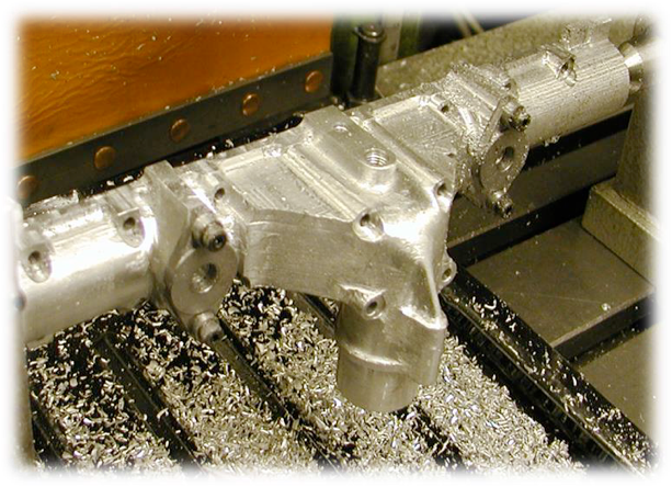
The hand finishing is a long and tedious process using burrs. To get into tight spots, files and emery cloth are used. Scotch Brite abrasive cloths are also used. When it is a good scratchless unblemished surface, it can be finished by bead blasting. All scratches and blemishes must be removed before bead blasting is considered, as it only gives an even surface like spraying paint. Scratches will still appear through it.
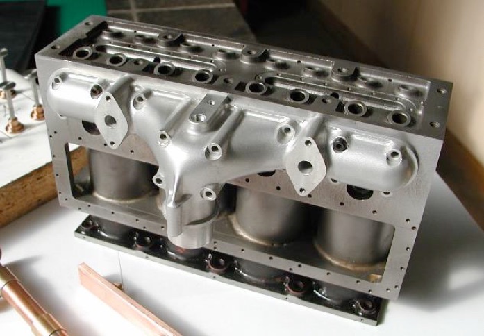
In Conclusion: Machining complex shapes from solid, if done in a careful and logical way, must always provide a more consistent finish and accurate shape than sand castings.
Only die cast or ‘lost wax’ castings can approach this accuracy and these are uneconomical for ‘one-offs’.






Modelengineeringwebsite.com
the only free and the only weekly magazine for model engineers.
Editor: David Carpenter