MACHINING ‘CASTINGS’ FROM SOLID
Part two by Mike Sayers


MACHINING ‘CASTINGS’ FROM SOLID
Part two by Mike Sayers

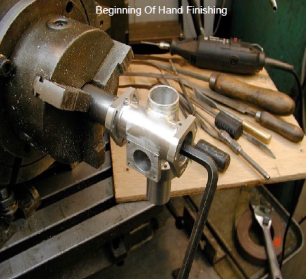
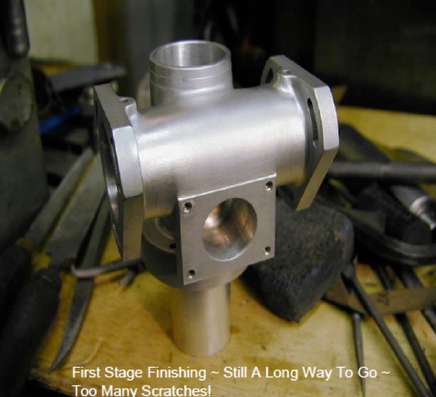
The photos below show the beginning of the hand finishing. Here the component is held in the bore by an expanded mandrel. The external areas are being filed and the radii are being blended. Thank goodness for the mighty Dremel and those cheap diamond coated burrs. The second photo show the component after the first stage finishing. It is adequate for the continuing machining operations.
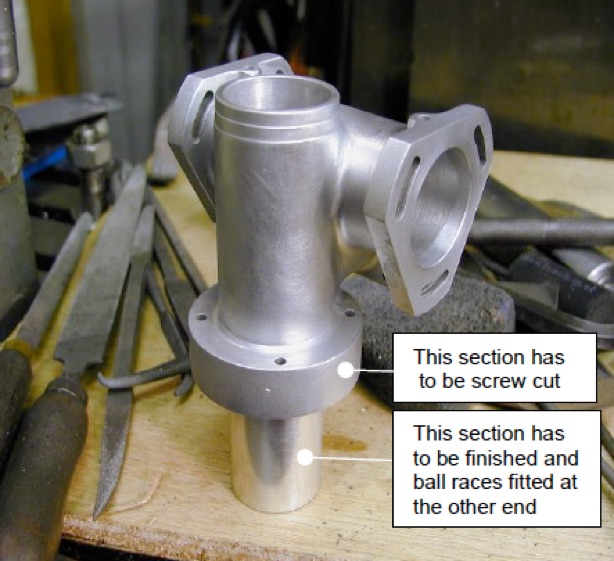
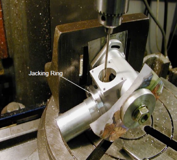
The magneto bore is chucked and the internal drain holes are being drilled for the oil that runs down the vertical shaft lubricating the nest of gears. All the oil that runs out of the cam box at the top, runs down the vertical shaft and finds its way out of the bottom to the sump.

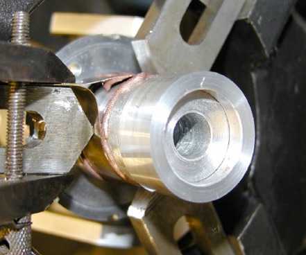
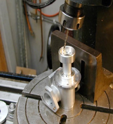
An unsealed open ball race sits inside the bore, seen at the top of the component in the orientation in the photo, and the oil passes through it on its way to the sump.
This next photo shows the component finished, with the gears assembled in it. Bearing sleeves, which are just bushes, are installed in the magneto bores and these support the centre gear. A bush has also been pressed into the back
of bore A to support the water pump drive gear. The flange piece that is fitted on flat face C has a bearing in it which supports the front of the shaft. The water pump shaft fits in the square hole The square hole in the water pump gear wheel has been broached out using a D-Bit.
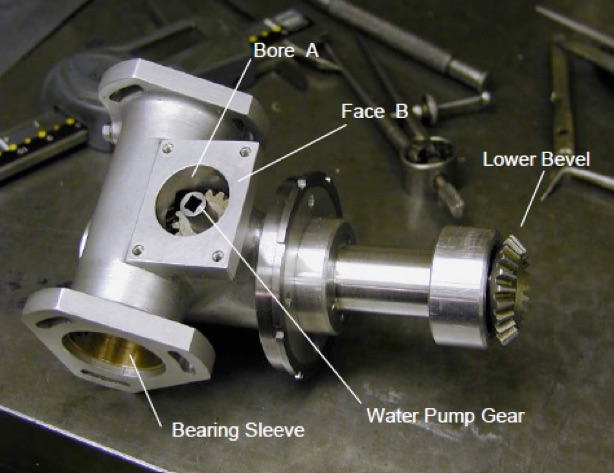
Next photo is the component assembled with the water pump, and the following photo shows the component mounted on the engine.
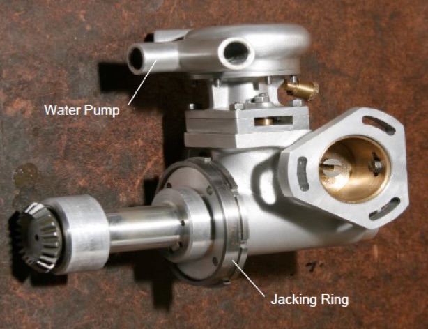
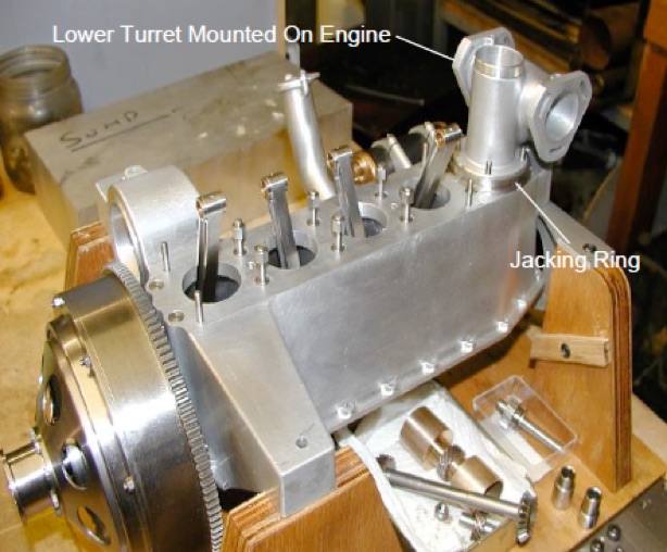
As shown previously, the bevel gear at the bottom is driven off the crankshaft bevel drive. Adjusting the jacking ring lifts or lowers the turret assembly to mesh the two bevel gears. This is how it is done on the full-scale engine. The longitudinal movement of the bottom bevel is achieved by shimming the thrust race in the crankshaft and that action moves the whole crankshaft back and forth by a few thou.
Component 1~ In Conclusion: All the datum points are within the component, but there are components where the datums that are needed aren’t within the component or are in an awkward position which can’t be used easily. To illustrate this point, let us look at the manifold (Component 2).
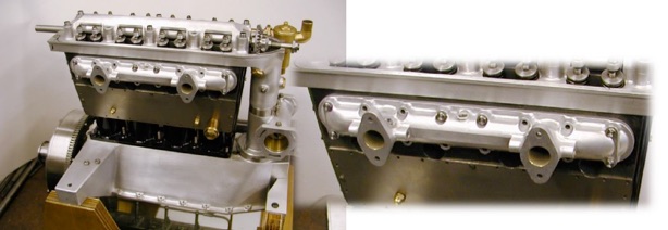
Component 2 ~ The Bentley 3 Litre engine manifold. Using datums external to the component.
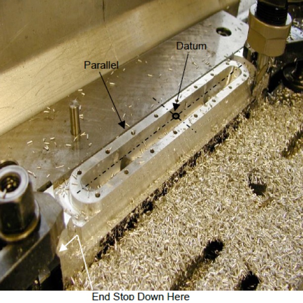
Centre lines are marked on the block, and the X and Y scales on the readout are zeroed to this origin. If all dimensions on the drawing have been prepared using this datum, as long as the end location is maintained and the block set against the fixed parallel, all the holes on each face will be maintained in the correct relationship to each other.
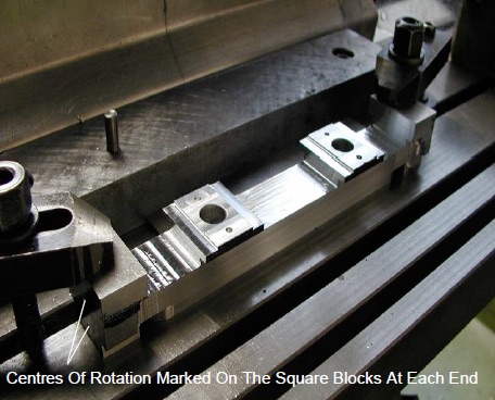
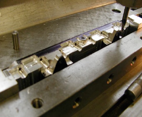

The whole job can be rotated by hand, under a cutter. This centre results in curved shapes at A, B and C.
Moving the centre of rotation to the upper centre allows the curved bosses at d,e,f and g to be machined. These curved bosses are on the axis of the throttle spindle. It may sound strange to have a throttle spindle in a manifold, but that is how the sloper carburettors 3 litre Bentleys work.There are no butterfies in the main part of the carburretor. The carburettors are bolted to the manifold and their butterflies sit inside the holes, so it is imperative the holes are in line.
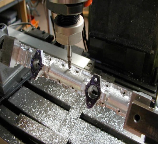
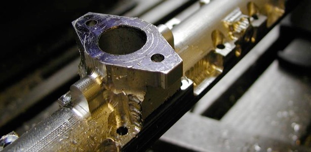
The carburettor butterfly spindle bosses are produced in the same way using the upper datum centres.
With an expanding mandrel in the inlet bores, the job is partially rotated to produce the short section of curve behind the carburettor manifold flange. Not all of this section is accessible to cut the curve, but most of it is. The technique is to machine as much as possible, and then ‘fudge’ the rest by hand.
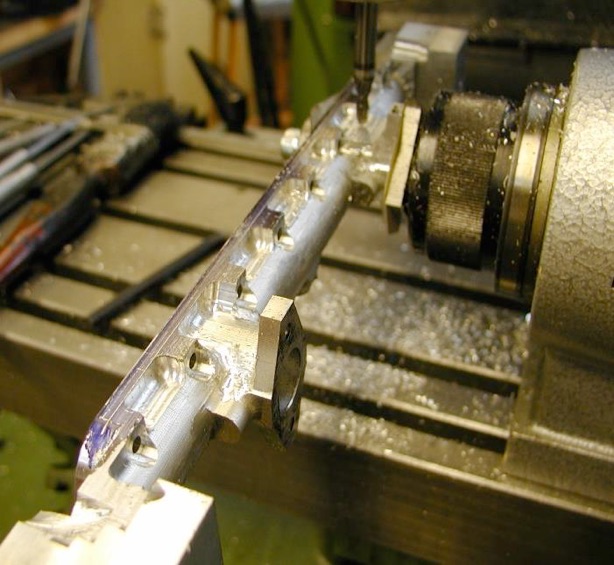
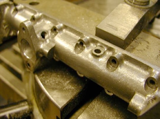
The photo above shows the rough finished part. The question now is, can the ‘squares’ now be removed? There is another process where the ‘square’s’ datum centres come into their own, and that is for drilling and reaming the carburettor butterfly spindle holes in line.
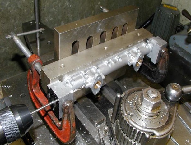
The upper datum centre (used to machine the curves on the bosses) has been centre drilled to a larger diameter, as the centre cone section is required when the component is reversed for the drilling of the second spindle hole. The drill can use this hole as a support to drill both spindle holes.
As can be seen, the brass sleeves are already installed in the carburettor manifold. The brass sleeves prevent the aluminium from wearing due to the operation of the butterflies.
This is representative of the full-scale engine. The ‘square ends’ can now be removed.
Component 2~ In Conclusion: The Manifold (Component 2) shows that having external references with flat faces for mounting the part when machining peculiarly shaped components, and which contain datum points for the step-by-step machining processes, makes the job so much easier and more accurate. It just requires more forethought at the planning stage of the job.