MACHINING ‘CASTINGS’ FROM SOLID
Part one by Mike Sayers


MACHINING ‘CASTINGS’ FROM SOLID
Part one by Mike Sayers

The question to start with is: Why would you want to machine ‘castings’?
Some answers are:
• You are building a project where castings are unavailable.
• You live in Yorkshire and are not prepared to spend the money purchasing them, even though they were available.
• You have no skill or enthusiasm for foundry work.
• Castings may not reach the quality of finish required.
There are several advantages:
• The machinist is in close control of all dimensions.
• There are no problems with inclusions or blowholes.
• There is a consistency of finish.
• The component will be stronger, because the material is stronger.
There are also several disadvantages:
• ‘Machinings’ require time consuming setups.
• A certain amount of tooling is required.
• ‘Machinings’ sometimes require tedious hand finishing.
•A drastic mistake when close to completion does not improve one’s temper.
To illustrate the concept let’s look at my 1:3 scale 3 litre Bentley Engine.
three components from the engine show the way to look at the shape of an original full-scale casting, before starting a scaled version machined from solid.
1. The lower turret of The 3 litre Bentley engine
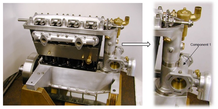
The turret performs the same function as an accessory drive on an aircraft engine. There is a water pump attached to it as well as two magnetos on either side. Inside, a vertical drive goes up through the turret to drive the cam shaft at the top.
The pump, magnetos, and the internal drive all function while attached to this one casting.
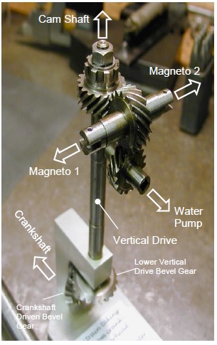
The upper gears are home-made cross helical gears.
The bottom bevel gear is connected onto the end of the crank shaft.
This drives the lower vertical drive bevel gear.
The upper vertical shaft cross helical gear drives the magneto helical gear in a ratio 1:1.
The magneto helical gear in turn drives the water pump helical gear below it. This is slightly over-driven being 30% over engine speed.
The vertical drive shaft and the two upper shaft centre positions are absolutely critical. The gearing was set up with the best running tolerances, and the shaft centres were measured so that the exact relationship between them was known. These dimensions were then incorporated in the drawing.
This meant that if the bores in the turret are accurately manufactured using the shaft centre dimensions, the gears will fit and run with minimum backlash. If it is too tight, they won’t go in.
To create the scale version of the cast turret, this important relationship between the bore centre lines is the starting point.
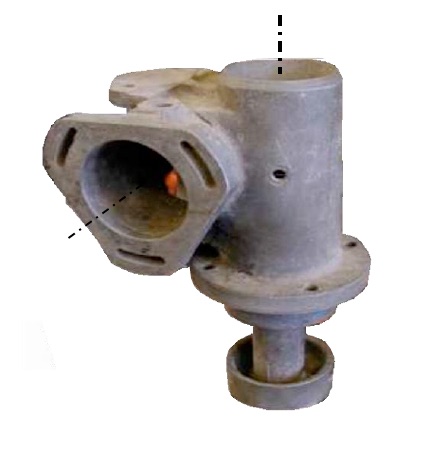
The relationship between the vertical and horizontal bores
have to be maintained on the scale model.
To start with, a block of metal is required.

The block has been machined to dimensions just over the minimum size to get the scale shape of the casting.
All the sides have been machined square and parallel, so if the block is stood in any plane, all the other sides will be upright and 90° to each other. This means that the sides can then be used as setting faces.
The ‘marking out’ shown above is the only marking required, to establish a centre line on the top face to give the approximate position of the vertical shaft.
The right-hand vertical line on the front face above, is also marked in relation to the vertical line on the left-hand side which aligns to the centre line of the vertical shaft. There is a similar approximate centre line for the water pump marked on the other side.
Eventually these centre lines must be precise. ‘Marking out’ is not accurate enough.
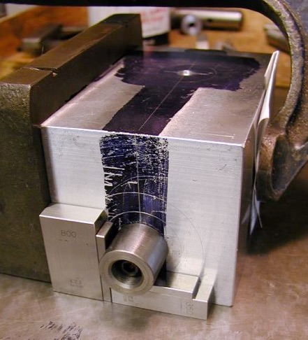
Working from the two reference faces, the base and the side, the button can then be accurately positioned, with its known height from the base and position from the side.
In positioning these buttons, the same reference base and side faces are always used, to produce accurate centre lines.
Toolmakers buttons are a bit old fashioned now, but are accurate in positioning bores.
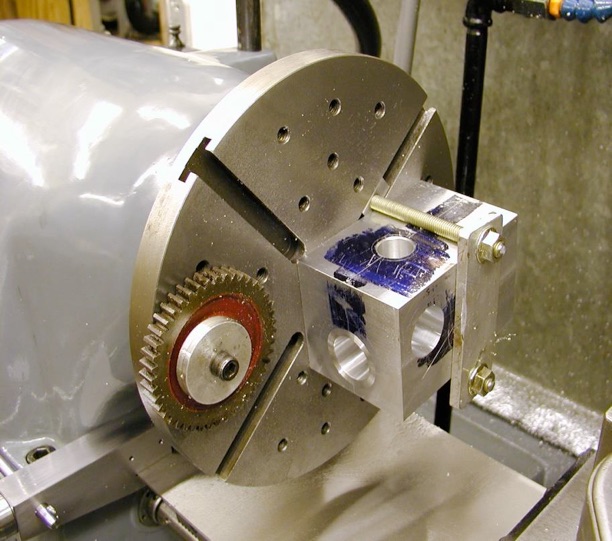
The block is then put in a four-jaw chuck and the button is clocked ‘true’.
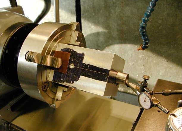
The first bore to be drilled is the vertical bore which doesn’t go all the way through. A D-bit is used to ‘true’ the bore so that when the hole comes out the other end it is in line with the other end.
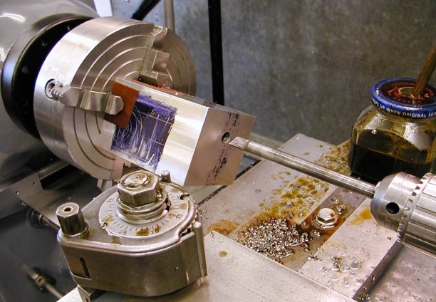
It doesn’t go all the way through.
It is bored to size and depth.
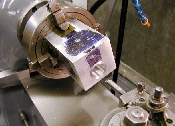
All the buttons have been positioned by the slip gauges from the reference faces as described for the vertical drive bore.
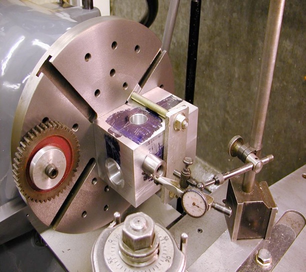
Every operation on the block from now on is chucked from a bore on an expanding mandrel or some similar means.
The reason for showing this particular component is that all the datum faces that are used are within the component, which makes it quite easy to follow through with all of the rest of the machining procedures.
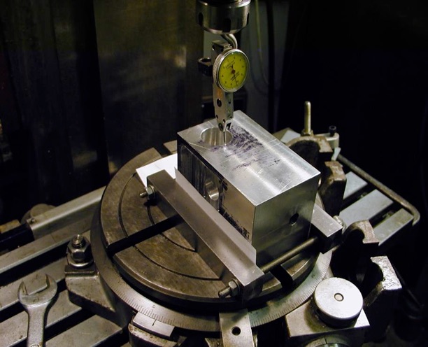
The size of the flange has been outlined and the stud holes have been drilled and tapped, all by co-ordinate measurement from the bore centre which has been clocked up true and the X and Y scales set to zero.
From that co-ordinate at the bore centre, all cutter and drill/tap operations have been carried out without ‘marking out’, but by using the ‘readout’ dimensions from that origin.

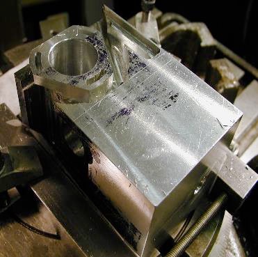
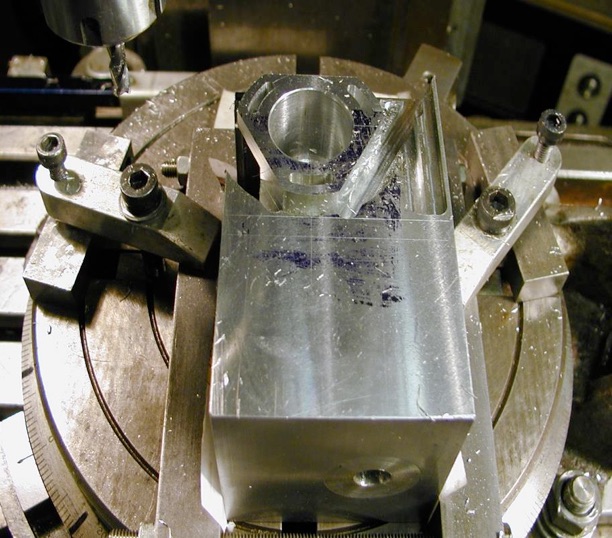
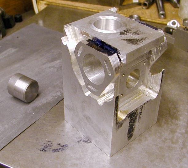
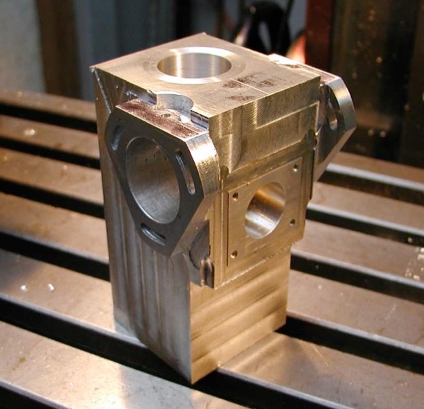
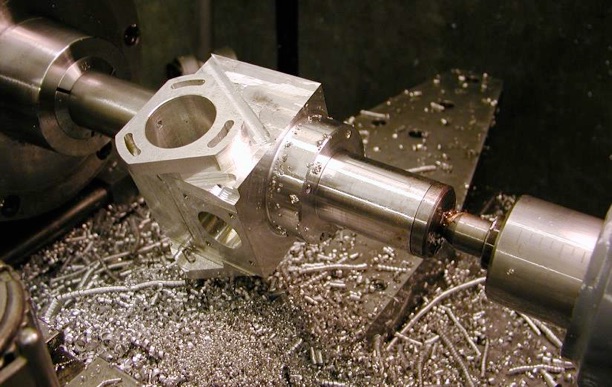
Section A is being turned as a stepped diameter.
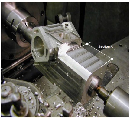
This allows the top to be machined.
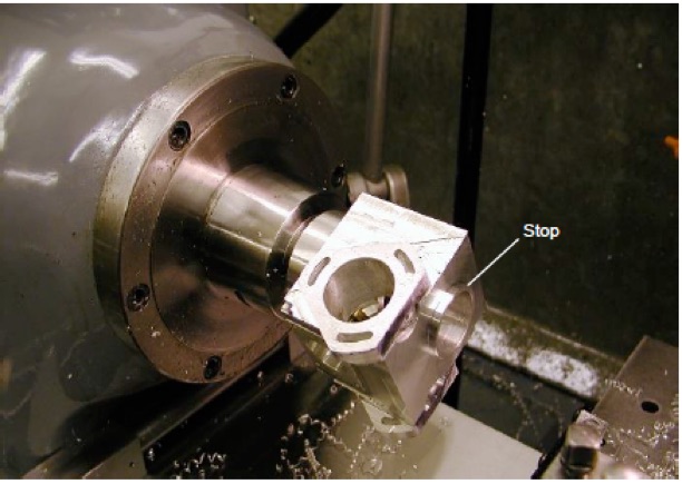

If you look at any component or casting, the combination of intersecting cylinders can be visualized, and it is that fact that needs to be appreciated before starting any machining. As it is being drawn, the means of holding and machining the component can be visualized. Some of the cylinders may only be part of a cylinder, but they are still there, and the curves have to be produced. The centre-line around which the component needs to be rotated to produce the curves still needs to be known. The previous photo shows the first stage in ‘roughing out’ the outer surface of this component.
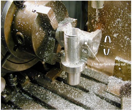
this time in the magneto bores, to rough cut the outer surface shown. This is hand rotated as before.
Not every position on the outer surface of the component
can be easily reached. The photo below shows work on a difficult area with an extended cutter, but note the interference with the component at A. Also note the excess material marked B which will have to worked on by other means.
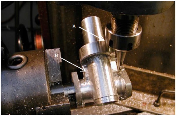
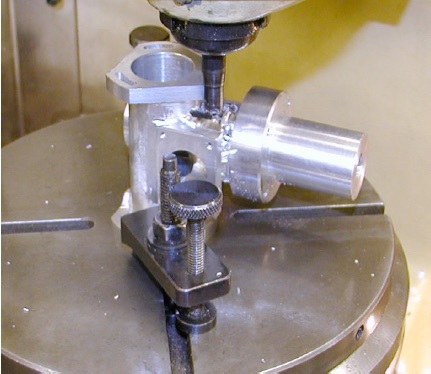
This is the limit of the machining on the exterior. It’s all down to hand finishing now.






Modelengineeringwebsite.com
the only free and the only weekly magazine for model engineers.
Editor: David Carpenter