USS MONITOR
ENGINE BUILD
Part 12 by Vince Cutajar



USS MONITOR
ENGINE BUILD
Part 12 by Vince Cutajar













Modelengineeringwebsite.com -
the only weekly magazine for model engineers
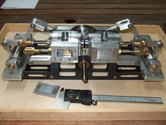
The USS Monitor was an ‘ironclad’ steam ship which famously saw service in the Civil War in the early 1860s. The ship's engine was designed by John Ericsson as a "vibrating side-lever engine." He had created similar engines before and decided to use the design again because of its advantage for a small, low-riding warship.
Most steam engines of the time had vertical pistons, which occupied a lot of space and made them vulnerable to enemy fire because they were partially above the waterline. In contrast, the Monitor's 30-ton, 400 horsepower engine had pistons that moved horizontally, which reduced the height of the engine and allowed it to be mounted below the waterline.
Although a successful fighting ship the Monitor was not stable in rough seas due to its formidable rotating turret and sank in the early hours of January 1, 1863.
The engine was recovered from the Monitor's wreck site in 2001. It is now resting upside-down in an alkaline solution to inhibit corrosion. Over the coming years, conservators will continue to clean and separate the many different pieces of the engine to preserve them properly.
The first model Monitor was shown at Harrogate in 2014 by Brian Stephenson to the design of Bob Middleton. It was built without castings, like Bob’s other designs. Julius de Waal has produced these CAD drawings for both metric and imperial (see here) versions. Drawings can be downloaded for personal use only.
This one is built to Julius’ metric drawings.
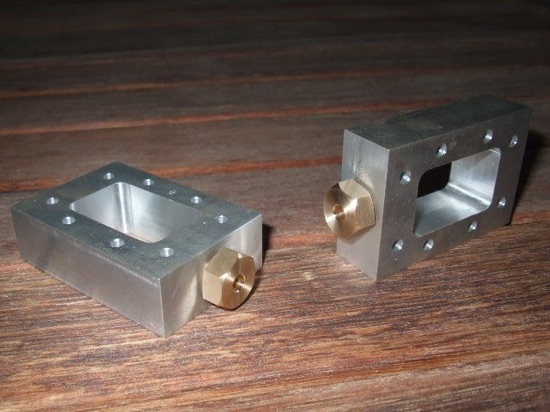
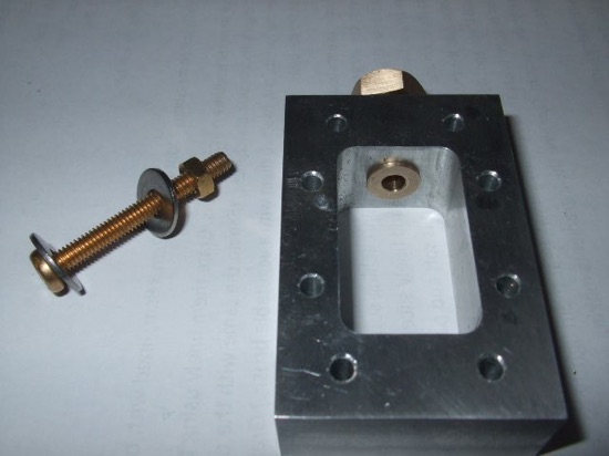
To fit the valve rod gland nut it was drilled and reamed 8mm. Then opened up the hole to 9mm with an slot drill to a depth of 8mm and then tapped 10 X 1mm for the gland nut.
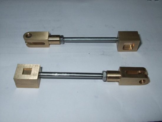
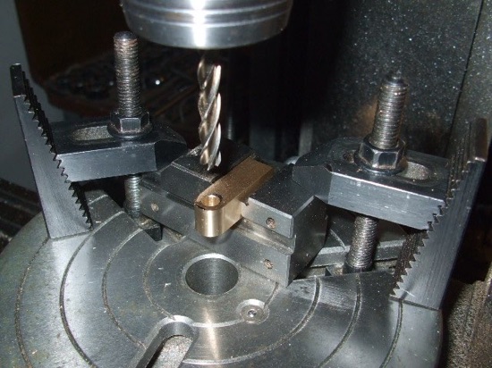
For the slide valve rod end I used the same method I used for the piston rod although when rounding off the end on the rotary table, this time I used a 1" vice to hold the part on the rotary table.
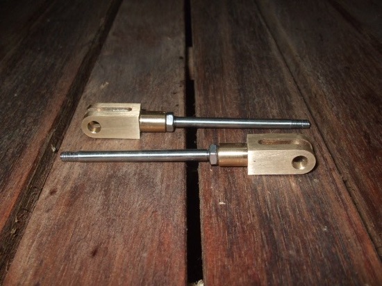
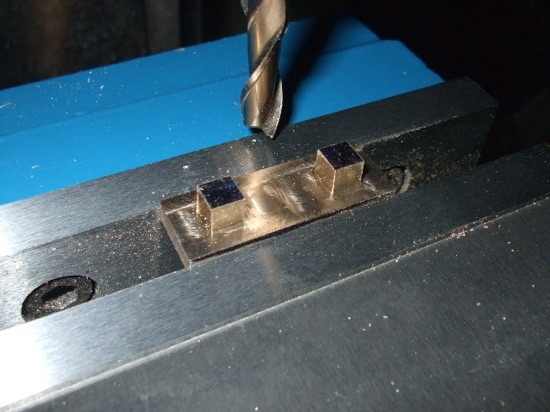
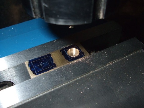
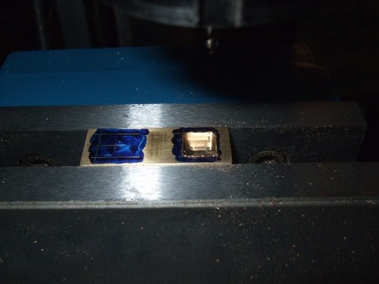
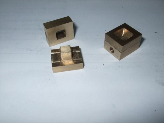
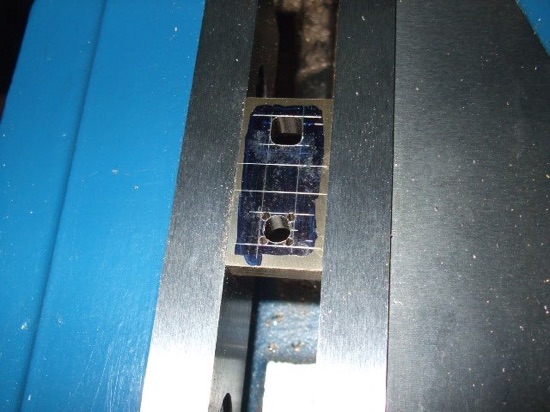
This requires a 6mm square hole in the brass material. Marked them out and did the first one by drilling a 5mm hole first to remove some waste material and then using a 3mm carbide slot drill made a series of plunge cuts with the quill at 0.1mm intervals. Sort of nibbling away at the material.
When I came to do the second one I added an extra step. I drilled a 1.5mm hole at the four corners so that I would have less filing to do at the corners.
Like the buckle I machined them both together. First the top of the valve. This is where the buckle is inserted.